Toyota Tacoma (2015-2018) Service Manual: Clutch Accumulator
Components
COMPONENTS
ILLUSTRATION
Installation
INSTALLATION
PROCEDURE
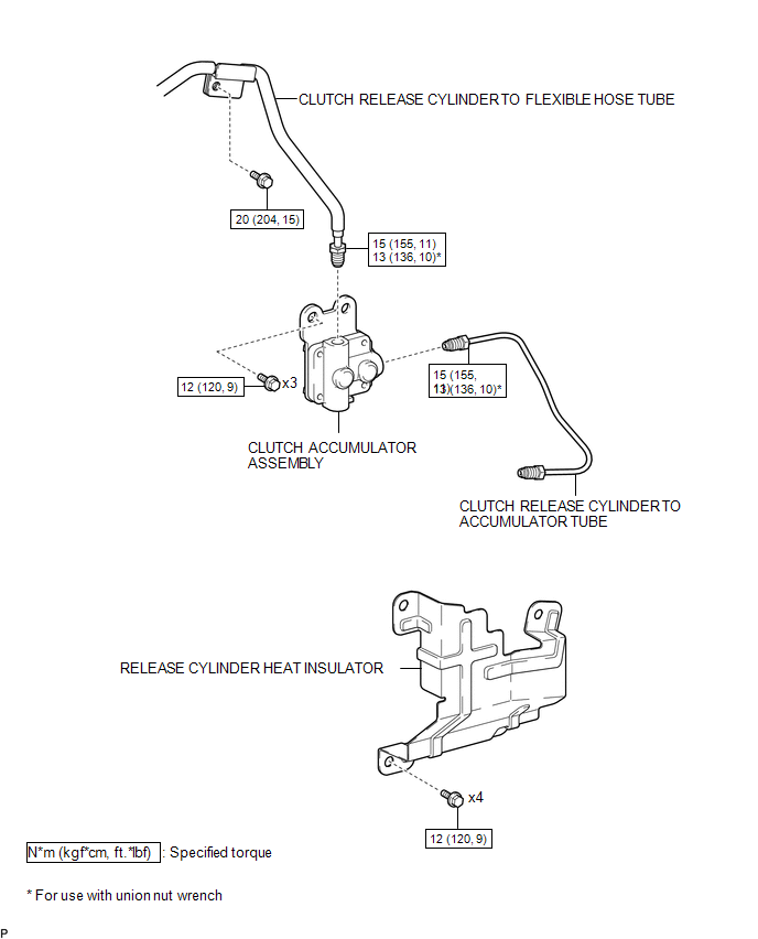
1. INSTALL CLUTCH ACCUMULATOR ASSEMBLY
(a) Install the clutch accumulator assembly to the manual transmission assembly with the 3 bolts.
Torque:
12 N·m {120 kgf·cm, 9 ft·lbf}
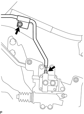
(b) Using a union nut wrench, connect the clutch release cylinder to flexible hose tube to the clutch accumulator assembly.
Torque:
Specified tightening torque :
15 N·m {155 kgf·cm, 11 ft·lbf}
HINT:
- Calculate the torque wrench reading when changing the fulcrum length
of the torque wrench (See page
.gif) ).
). - When using a union nut wrench (fulcrum length of 22 mm (0.866 in.)) + torque wrench (fulcrum length of 162 mm (6.38 in.)): 13 N*m (136 kgf*cm, 10 ft.*lbf)
(c) Install the clutch release cylinder to flexible hose tube to the manual transmission assembly with the bolt.
Torque:
20 N·m {204 kgf·cm, 15 ft·lbf}
2. INSTALL CLUTCH RELEASE CYLINDER TO ACCUMULATOR TUBE
3. INSTALL RELEASE CYLINDER HEAT INSULATOR
4. INSTALL FRONT PROPELLER SHAFT ASSEMBLY
(See page )
5. FILL RESERVOIR WITH BRAKE FLUID
6. BLEED CLUTCH LINE
7. CHECK FLUID LEVEL IN RESERVOIR
8. INSPECT FOR CLUTCH FLUID LEAK
Removal
REMOVAL
PROCEDURE
1. DRAIN CLUTCH FLUID
2. REMOVE FRONT PROPELLER SHAFT ASSEMBLY
(See page .gif) )
)
3. REMOVE RELEASE CYLINDER HEAT INSULATOR
4. REMOVE CLUTCH RELEASE CYLINDER TO ACCUMULATOR TUBE
5. REMOVE CLUTCH ACCUMULATOR ASSEMBLY
|
(a) Using a union nut wrench, disconnect the clutch release cylinder to flexible hose tube from the clutch accumulator assembly. HINT: Use a container to catch the fluid. |
|
(b) Remove the bolt and separate the clutch release cylinder to flexible hose tube from the manual transmission assembly.
|
(c) Remove the 3 bolts and clutch accumulator assembly from the manual transmission assembly. |
|

 Clutch
...
 Clutch Master Cylinder
Components
COMPONENTS
ILLUSTRATION
Installation
INSTALLATION
PROCEDURE
1. INSTALL CLUTCH MASTER CYLINDER ASSEMBLY
(a) Install the clutch master cylinder assembly to the clutch pedal suppo ...
Other materials:
Short to GND in Outer Mirror Indicator(Slave) (C1AB3)
DESCRIPTION
This DTC is stored when the blind spot monitor sensor RH detects a ground short
in the blind spot monitor indicator RH.
DTC Code
DTC Detection Condition
Trouble Area
C1AB3
With the blind spot monitor main switch assembly (w ...
Reassembly
REASSEMBLY
CAUTION / NOTICE / HINT
HINT:
The procedure described below is for the LH side. Use the same procedure for
both the LH and RH sides, unless otherwise specified.
PROCEDURE
1. INSTALL REAR SEAT CUSHION FRAME SUB-ASSEMBLY
(a) Install the rear seat cushion frame sub-assembl ...
Trailer towing
Your vehicle is designed primarily as a passenger-and-load-carrying vehicle.
Towing a trailer can have an adverse impact on handling, performance, braking, durability,
and fuel consumption. For your safety and the safety of others, you must not overload
your vehicle or trailer. You must also e ...
