Toyota Tacoma (2015-2018) Service Manual: Clearance Warning Buzzer
Components
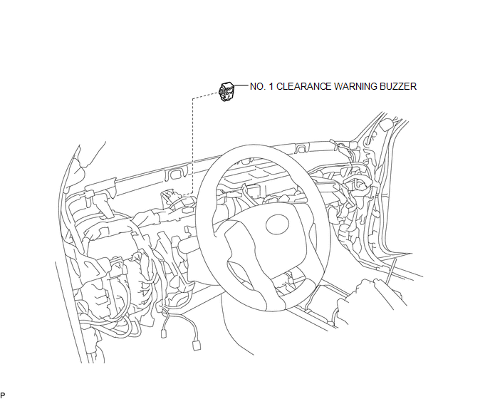
COMPONENTS
ILLUSTRATION
Installation
INSTALLATION
PROCEDURE
1. INSTALL NO. 1 CLEARANCE WARNING BUZZER
(a) Connect the connector.
(b) Engage the clamp to install the No. 1 clearance warning buzzer.
2. INSTALL INSTRUMENT PANEL SUB-ASSEMBLY
(See page .gif) )
)
Removal
REMOVAL
PROCEDURE
1. REMOVE INSTRUMENT PANEL SUB-ASSEMBLY
(See page .gif) )
)
2. REMOVE NO. 1 CLEARANCE WARNING BUZZER
|
(a) Disengage the clamp. |
|
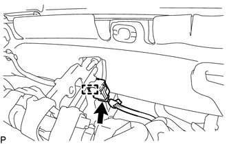
(b) Disconnect the connector to remove the No. 1 clearance warning buzzer.
 Clearance Sonar Main Switch
Components
COMPONENTS
ILLUSTRATION
Removal
REMOVAL
PROCEDURE
1. REMOVE INSTRUMENT PANEL LOWER CENTER FINISH PANEL
(See page )
2. REMOVE BACK SONAR OR CLEARANCE SONAR SWITCH ASSEMBLY
...
 Clearance Warning Ecu
Components
COMPONENTS
ILLUSTRATION
Installation
INSTALLATION
PROCEDURE
1. INSTALL CLEARANCE WARNING ECU ASSEMBLY
(a) Connect the connector.
(b) Engage the 2 guides to install the clearan ...
Other materials:
VSC Buzzer Circuit
DESCRIPTION
The skid control ECU (brake actuator assembly) is connected to the combination
meter via CAN communication.
The combination meter has a built-in VSC warning buzzer:
Sounds intermittently to inform the driver if the temperature of brake
actuator assembly has increased exce ...
Lost Communication with ECM (U0100,U0142,U0155)
DESCRIPTION
DTC No.
DTC Detecting Condition
Trouble Area
U0100
No communication with ECM
CAN communication system
ECM
U0142
No communication with main body ECU
...
Vehicle Speed Tolerance Malfunction (C1AA2)
DESCRIPTION
The forward recognition camera receives vehicle speed tolerance signals from
the combination meter assembly. If the combination meter assembly detects a vehicle
speed tolerance malfunction signal, it informs the forward recognition camera via
CAN communication, and DTC C1AA2 is st ...
