Toyota Tacoma (2015-2018) Service Manual: Center Airbag Sensor Assembly
Components
COMPONENTS
ILLUSTRATION
On-vehicle Inspection
ON-VEHICLE INSPECTION
PROCEDURE
1. INSPECT AIRBAG SENSOR ASSEMBLY (for Vehicle not Involved in Collision)
(a) Perform a diagnostic system check (See page
.gif) ).
).
2. INSPECT AIRBAG SENSOR ASSEMBLY (for Vehicle Involved in Collision and Airbag has not Deployed)
(a) Perform a diagnostic system check (See page
).
3. INSPECT AIRBAG SENSOR ASSEMBLY (for Vehicle Involved in Collision and Airbag has Deployed)
(a) Replace the airbag sensor assembly.
CAUTION:
For removal and installation procedures of the airbag sensor assembly, be sure to follow the correct procedure.
HINT:
The airbag sensor assembly should be replaced after any of the airbags has deployed, as it has been subjected to the impact.
Removal
REMOVAL
PROCEDURE
1. PRECAUTION
CAUTION:
Be sure to read Precaution thoroughly before servicing (See page
.gif) ).
).
NOTICE:
After turning the ignition switch off, waiting time may be required before disconnecting the cable from the negative (-) battery terminal. Therefore, make sure to read the disconnecting the cable from the negative (-) battery terminal notices before proceeding with work.
Click here
2. DISCONNECT CABLE FROM NEGATIVE BATTERY TERMINAL
CAUTION:
Wait at least 90 seconds after disconnecting the cable from the negative (-) battery terminal to prevent airbag and seat belt pretensioner activation.
NOTICE:
When disconnecting the cable, some systems need to be initialized after the cable is reconnected.
Click here
3. REMOVE FRONT CONSOLE BOX
Click here
4. REMOVE AIRBAG SENSOR ASSEMBLY
(a) Check that the ignition switch is OFF.
(b) Check that the cable is disconnected from the battery negative (-) terminal.
CAUTION:
Wait at least 90 seconds after disconnecting the cable from the negative (-) battery terminal to prevent airbag and seat belt pretensioner activation.
|
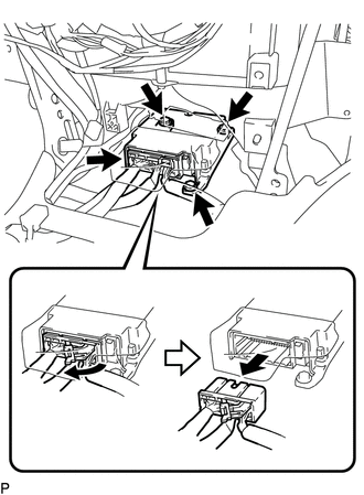
(c) Pull the lever down to disconnect the connector holder. |
|
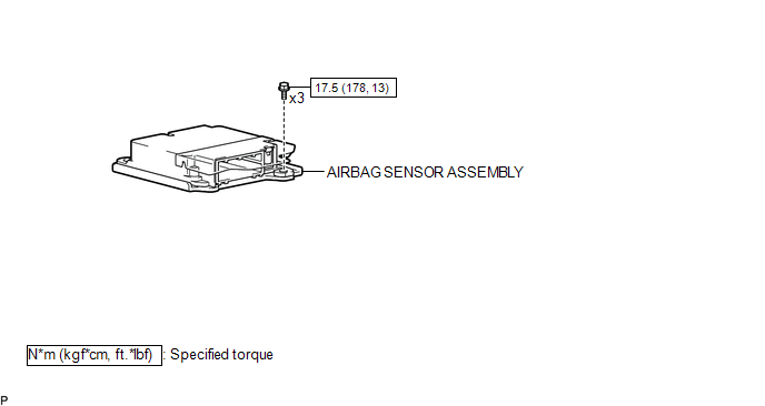
(d) Remove the 3 bolts and airbag sensor assembly.
Installation
INSTALLATION
PROCEDURE
1. INSTALL AIRBAG SENSOR ASSEMBLY
(a) Check that the ignition switch is OFF.
(b) Check that the cable is disconnected from the battery negative (-) terminal.
CAUTION:
Wait at least 90 seconds after disconnecting the cable from the negative (-) battery terminal to prevent airbag and seat belt pretensioner activation.
(c) Install the airbag sensor assembly with the 3 bolts.
Torque:
17.5 N·m {178 kgf·cm, 13 ft·lbf}
NOTICE:
- If the airbag sensor assembly has been dropped, or there are any cracks, dents or other defects in the case, bracket or connector, replace it with a new one.
- When installing the airbag sensor assembly, be careful that the SRS wiring does not interfere with other parts and that it is not pinched between other parts.
(d) Check that there is no looseness in the installation parts of the airbag sensor assembly.
|
(e) Connect the connector holder to lock the lever. Text in Illustration
NOTICE: Confirm that the lever is locked. |
|
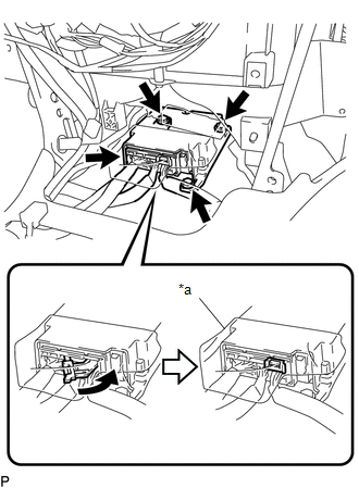
(f) Check that the waterproof sheet is properly set.
2. INSTALL FRONT CONSOLE BOX
Click here .gif)
3. CONNECT CABLE TO NEGATIVE BATTERY TERMINAL
Torque:
5.4 N·m {55 kgf·cm, 48 in·lbf}
NOTICE:
When disconnecting the cable, some systems need to be initialized after the cable is reconnected.
Click here
4. INSPECT SRS WARNING LIGHT
Click here
 TC and CG Terminal Circuit
DESCRIPTION
DTC output mode is set by connecting terminals TC and CG of the DLC3.
The DTCs are displayed by blinking the SRS warning light.
HINT:
Make sure that DTCs which relate to the CA ...

Other materials:
Removal
REMOVAL
PROCEDURE
1. PRECAUTION
CAUTION:
Be sure to read Precaution thoroughly before servicing (See page
).
NOTICE:
After turning the ignition switch off, waiting time may be required before disconnecting
the cable from the negative (-) battery terminal. Therefore, make sure to read the
...
Adjustment
ADJUSTMENT
PROCEDURE
1. BEFORE FILLING TRANSMISSION
The AC60E automatic transmission assembly requires Toyota Genuine ATF
WS.
If the entire automatic transmission assembly, automatic transmission
oil pan sub-assembly, drain plug, transmission valve body assembly and/or
torq ...
Freeze Frame Data
FREEZE FRAME DATA
DESCRIPTION
(a) Whenever a lane departure alert system is stored, the forward recognition
camera stores the current vehicle state (ECU and sensor information) as Freeze Frame
Data.
CHECK FREEZE FRAME DATA
(a) Connect the Techstream to the DLC3.
(b) Turn the ignition switch ...
