Toyota Tacoma (2015-2018) Service Manual: Cargo Light
Components
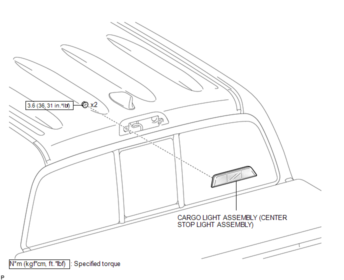
COMPONENTS
ILLUSTRATION
Removal
REMOVAL
PROCEDURE
1. REMOVE ROOF HEADLINING ASSEMBLY
- for Double Cab:
(See page
.gif) )
) - for Access Cab:
(See page
)
2. REMOVE CARGO LIGHT ASSEMBLY (CENTER STOP LIGHT ASSEMBLY)
|
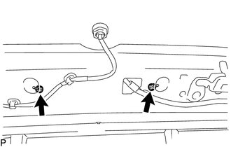
(a) Remove the 2 nuts. |
|
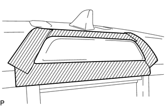
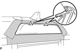
(b) Apply protective tape around the cargo light assembly (center stop light assembly).
 Text in Illustration
.png) |
Protective Tape |
|
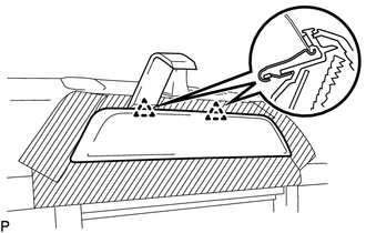
(c) Using a moulding remover D, disengage the 2 clips to separate the cargo light assembly (center stop light assembly). |
|
|
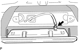
(d) Disconnect the connector to remove the cargo light assembly (center stop light assembly). |
|
Inspection
INSPECTION
PROCEDURE
1. INSPECT CARGO LIGHT ASSEMBLY (CENTER STOP LIGHT ASSEMBLY)
(a) Check the illuminates.
|
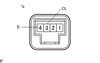
(1) Apply battery voltage to the connector and check the light illumination condition. Text in Illustration
OK:
If the result is not as specified, replace the cargo light assembly (center stop light assembly). |
|
Installation
INSTALLATION
PROCEDURE
1. INSTALL CARGO LIGHT ASSEMBLY (CENTER STOP LIGHT ASSEMBLY)
(a) Connect the connector.
|
(b) Engage the 2 clips to install the cargo light assembly (center stop light assembly). |
|
(c) Install the 2 nuts.
Torque:
3.6 N·m {36 kgf·cm, 31 in·lbf}
(d) Remove the protective tape.
2. INSPECT ROOF HEADLINING ASSEMBLY
- for Double Cab:
(See page
.gif) )
) - for Access Cab:
(See page
)
 Automatic Light Control Sensor
Components
COMPONENTS
ILLUSTRATION
Installation
INSTALLATION
PROCEDURE
1. INSTALL AUTOMATIC LIGHT CONTROL SENSOR
(a) Engage the 2 claws to install the automatic light control sensor.
2. ...
 Cargo Light Switch
Components
COMPONENTS
ILLUSTRATION
Inspection
INSPECTION
PROCEDURE
1. INSPECT DECK LIGHT SWITCH ASSEMBLY
(a) Check the resistance.
(1) Measure the resistance according to the ...
Other materials:
Clutch Switch
Components
COMPONENTS
ILLUSTRATION
Removal
REMOVAL
PROCEDURE
1. PRECAUTION
NOTICE:
After turning the engine switch off, waiting time may be required before disconnecting
the cable from the battery terminal. Therefore, make sure to read the disconnecting
the cable from the battery t ...
Data List / Active Test
DATA LIST / ACTIVE TEST
1. ACTIVE TEST
HINT:
Using the Techstream to perform Active Tests allows relays, VSVs, actuators and
other items to be operated without removing any parts. This non-intrusive functional
inspection can be very useful because intermittent operation may be discovered befo ...
System Description
SYSTEM DESCRIPTION
1. SYSTEM DESCRIPTION
The following pattern will be used: "Operation" indicates user operation using
the smart key system. "Expected operation of the vehicle" indicates how a known
good vehicle will react in accordance with each operation. "Suspected ...
