Toyota Tacoma (2015-2018) Service Manual: Automatic Disconnecting Differential Motor Limit Switch Circuit (P17A4)
DESCRIPTION
When the A.D.D. actuator switches between 2WD and 4WD, the DL1 and DL2 terminals of the limit switch and ADD terminal of the A.D.D. position switch change to one of the following ON/OFF combinations listed in the table below.
|
Terminal |
In 2WD |
Switching between 2WD and 4WD |
In 4WD |
|
|---|---|---|---|---|
|
DL1 |
ON (GND) |
ON (GND) |
OFF (OPEN) |
|
|
DL2 |
OFF (OPEN) |
ON (GND) |
ON (GND) |
|
|
ADD |
OFF (OPEN) |
OFF (OPEN) |
ON (GND) |
ON (GND) |
A malfunction is detected depending on the combination of the 3 circuits that make up the limit switch and A.D.D. position switch.
|
DTC No. |
Detection Item |
DTC Detection Condition |
Trouble Area |
|---|---|---|---|
|
P17A4 |
Automatic Disconnecting Differential Motor Limit Switch Circuit |
|
|
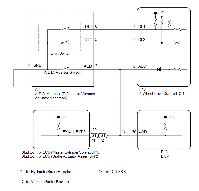
WIRING DIAGRAM
PROCEDURE
|
1. |
CHECK HARNESS AND CONNECTOR (4 WHEEL DRIVE CONTROL ECU - DIFFERENTIAL VACUUM ACTUATOR ASSEMBLY) |
(a) Disconnect the F13 4 wheel drive control ECU connector.
(b) Disconnect the A3 A.D.D. actuator (differential vacuum actuator assembly) connector.
(c) for Hydraulic Brake Booster:
Disconnect the S1 skid control ECU (Master Cylinder Solenoid) connector.
for Vacuum Brake Booster:
Disconnect the S1 skid control ECU (brake actuator assembly) connector.
(d) for 2GR-FKS:
Disconnect the E13 ECM connector.
(e) Measure the resistance according to the value(s) in the table below.
Standard Resistance:
|
Tester Connection |
Condition |
Specified Condition |
|---|---|---|
|
F13-8 (DL1) - A3-6 (DL1) |
Always |
Below 1 Ω |
|
F13-7 (DL2) - A3-5 (DL2) |
Always |
Below 1 Ω |
|
F13-2 (ADD) - A3-3 (ADD) |
Always |
Below 1 Ω |
|
A3-4 (GND) - Body ground |
Always |
Below 1 Ω |
|
F13-8 (DL1) or A3-6 (DL1) - Body ground |
Always |
10 kΩ or higher |
|
F13-7 (DL2) or A3-5 (DL2) - Body ground |
Always |
10 kΩ or higher |
|
F13-2 (ADD) or A3-3 (ADD) - Body ground |
Always |
10 kΩ or higher |
| NG | .gif) |
REPAIR OR REPLACE HARNESS OR CONNECTOR |
|
.gif)
|
2. |
INSPECT DIFFERENTIAL VACUUM ACTUATOR ASSEMBLY (LIMIT SWITCH AND A.D.D. POSITION SWITCH) |
|
(a) Disconnect the A.D.D. actuator (differential vacuum actuator assembly) connector. |
|
(b) for Hydraulic Brake Booster:
Disconnect the S1 skid control ECU (Master Cylinder Solenoid) connector.
for Vacuum Brake Booster:
Disconnect the S1 skid control ECU (brake actuator assembly) connector.
(c) for 2GR-FKS:
Disconnect the E13 ECM connector.
(d) Measure the voltage according to the value(s) in the table below.
Standard Voltage:
|
Tester Connection |
Switch Condition |
Specified Condition |
|---|---|---|
|
A3-6 (DL1) - Body ground |
Ignition switch ON |
10 to 14 V |
|
A3-5 (DL2) - Body ground |
Ignition switch ON |
10 to 14 V |
|
A3-3 (ADD) - Body ground |
Ignition switch ON |
10 to 14 V |
|
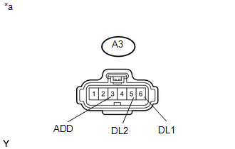
*a |
Front view of wire harness connector (to A.D.D. Actuator (Differential Vacuum Actuator Assembly)) |
| OK | |
REPLACE DIFFERENTIAL VACUUM ACTUATOR ASSEMBLY |
| NG | |
REPLACE 4 WHEEL DRIVE CONTROL ECU |
 Automatic Disconnecting Differential Motor Control Circuit Open (P17A0)
DESCRIPTION
This DTC is output when an open circuit in the A.D.D. shift motor drive circuit
is detected.
DTC No.
Detection Item
DTC Detection Condition
...
 Transfer Shift Motor Control Circuit Circuit Open (P17A8)
DESCRIPTION
This DTC is output when an open circuit in the transfer shift motor drive circuit
is detected.
DTC No.
Detection Item
DTC Detection Condition
...
Other materials:
Dtc Check / Clear
DTC CHECK / CLEAR
1. CHECK DTC (for TIRE PRESSURE WARNING ECU AND RECEIVER) (USING TECHSTREAM)
(a) Turn the ignition switch off.
(b) Connect the Techstream to the DLC3.
(c) Turn the ignition switch to ON.
(d) Turn the Techstream on.
(e) Enter the following menus: Chassis / Tire Pressure Monito ...
Components
COMPONENTS
ILLUSTRATION
*1
INSTRUMENT LOWER PANEL ASSEMBLY
*2
INSTRUMENT PANEL LOWER CENTER FINISH PANEL
*3
NO. 2 INSTRUMENT PANEL GARNISH SUB-ASSEMBLY
*4
REAR NO. 2 POWER WINDOW REGULATOR SWITCH ASSEMB ...
Adjustment
ADJUSTMENT
PROCEDURE
1. PREPARE VEHICLE FOR FOG LIGHT AIMING ADJUSTMENT
(a) Prepare the vehicle:
HINT:
Ensure that there is no damage or deformation to the body around the
fog lights.
Fill the fuel tank.
Make sure that the oil is filled to the specified level.
Make sure ...
