Toyota Tacoma (2015-2018) Service Manual: Automatic Disconnecting Differential Motor Control Circuit Open (P17A0)
DESCRIPTION
This DTC is output when an open circuit in the A.D.D. shift motor drive circuit is detected.
|
DTC No. |
Detection Item |
DTC Detection Condition |
Trouble Area |
|---|---|---|---|
|
P17A0 |
Automatic Disconnecting Differential Motor Control Circuit Open |
|
|
WIRING DIAGRAM
Refer to DTC P17A9 (See page .gif) ).
).
PROCEDURE
|
1. |
CHECK HARNESS AND CONNECTOR (4 WHEEL DRIVE CONTROL ECU - DIFFERENTIAL VACUUM ACTUATOR ASSEMBLY) |
(a) Disconnect the F12 4 wheel drive control ECU connector.
(b) Disconnect the A3 A.D.D. actuator (differential vacuum actuator assembly) connector.
(c) Measure the resistance according to the value(s) in the table below.
Standard Resistance:
|
Tester Connection |
Condition |
Specified Condition |
|---|---|---|
|
F12-2 (DM1) - A3-1 (DM1) |
Always |
Below 1 Ω |
|
F12-6 (DM2) - A3-2 (DM2) |
Always |
Below 1 Ω |
| NG | .gif) |
REPAIR OR REPLACE HARNESS OR CONNECTOR |
|
.gif)
|
2. |
INSPECT DIFFERENTIAL VACUUM ACTUATOR ASSEMBLY (A.D.D. SHIFT MOTOR) |
|
(a) Disconnect the A3 A.D.D. actuator (differential vacuum actuator assembly) connector. |
|
(b) Measure the resistance according to the value(s) in the table below.
Standard Resistance:
|
Tester Connection |
Condition |
Specified Condition |
|---|---|---|
|
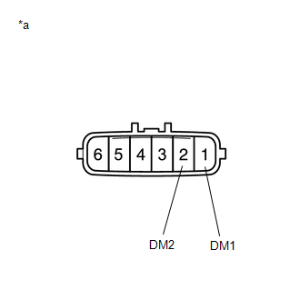
1 (DM1) - 2 (DM2) |
Always |
1.5 to 10 Ω |
|
*a |
Component without harness connected (A.D.D. Actuator (Differential Vacuum Actuator Assembly)) |
| OK | |
REPLACE 4 WHEEL DRIVE CONTROL ECU |
| NG | |
REPLACE DIFFERENTIAL VACUUM ACTUATOR ASSEMBLY |
 Invalid Data Received From Vehicle Dynamics Control Module (U0416)
DESCRIPTION
This DTC is detected if a wheel speed malfunction signal is sent from the skid
control ECU (brake actuator assembly).
DTC No.
Detection Item
DTC Detect ...
 Automatic Disconnecting Differential Motor Limit Switch Circuit (P17A4)
DESCRIPTION
When the A.D.D. actuator switches between 2WD and 4WD, the DL1 and DL2 terminals
of the limit switch and ADD terminal of the A.D.D. position switch change to one
of the following ON/O ...
Other materials:
Indicators and warning lights
The indicator and warning lights on the instrument cluster and center panel
inform the driver of the status of the vehicle’s various systems.
Instrument cluster
Center panel
■ Indicators
The indicators inform the driver of the operating state of the vehicle’s various
systems. ...
Data List / Active Test
DATA LIST / ACTIVE TEST
1. DATA LIST
HINT:
Using the Techstream to read the Data List allows the values or states of switches,
sensors, actuators and other items to be read without removing any parts. This non-intrusive
inspection can be very useful because intermittent conditions or signals ...
Dtc Check / Clear
DTC CHECK / CLEAR
CHECK FOR DTC
(a) Connect the Techstream to the DLC3.
(b) Turn the ignition switch to ON.
(c) Turn the Techstream on.
(d) Enter the following menus: Body Electrical / Central Gateway / Trouble Codes.
(e) Read the DTCs.
CLEAR DTC
(a) Connect the Techstream to the DLC3.
(b) ...
