Toyota Tacoma (2015-2018) Service Manual: Air Outlet Damper Control Servo Motor Circuit (B1443/43)
DESCRIPTION
This No. 1 air conditioning radiator damper servo sub-assembly (for mode switching) is controlled by the air conditioning amplifier assembly and moves the mode damper to the desired position.
|
DTC No. |
DTC Detection Condition |
Trouble Area |
|---|---|---|
|
B1443/43 |
Mode damper position sensor value does not change even if air conditioning amplifier assembly operates mode damper servo motor. |
|
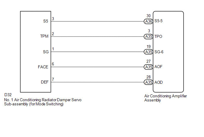
WIRING DIAGRAM
PROCEDURE
|
1. |
READ VALUE USING TECHSTREAM |
(a) Connect the Techstream to the DLC3.
(b) Turn the ignition switch to ON.
(c) Turn the Techstream on.
(d) Operate the mode switch.
(e) Enter the following menus: Body Electrical / Air Conditioner / Data List.
(f) Check the value(s) by referring to the table below.
Air Conditioner|
Tester Display |
Measurement Item/Range |
Normal Condition |
Diagnostic Note |
|---|---|---|---|
|
Air Outlet Damper Position |
Mode damper servo motor actual position / Min.: -14.0% Max.: 113.5% |
FACE: 0.0% DEF: 100.0% |
- |
|
Air Outlet Damper Target |
Mode damper servo motor target position / Min.: -14.0% Max.: 113.5% |
FACE: 0.0% DEF: 100.0% |
- |
OK:
The display is as specified in the Normal Condition column.
|
Result |
Proceed to |
|---|---|
|
NG |
A |
|
OK (When troubleshooting according to Problem Symptoms Table) |
B |
|
OK (When troubleshooting according to the DTC) |
C |
| B | .gif) |
PROCEED TO NEXT SUSPECTED AREA SHOWN IN PROBLEM SYMPTOMS TABLE |
| C | |
REPLACE AIR CONDITIONING AMPLIFIER ASSEMBLY |
|
.gif)
|
2. |
INSPECT NO. 1 AIR CONDITIONING RADIATOR DAMPER SERVO SUB-ASSEMBLY (FOR MODE SWITCHING) |
(a) Remove the No. 1 air conditioning radiator damper servo sub-assembly (for
mode switching) (See page .gif) ).
).
(b) Inspect the No. 1 air conditioning radiator damper servo sub-assembly (for
mode switching) (See page ).
| NG | |
REPLACE NO. 1 AIR CONDITIONING RADIATOR DAMPER SERVO SUB-ASSEMBLY (FOR MODE SWITCHING) |
|
|
3. |
CHECK HARNESS AND CONNECTOR (NO. 1 AIR CONDITIONING RADIATOR DAMPER SERVO SUB-ASSEMBLY - AIR CONDITIONING AMPLIFIER ASSEMBLY) |
(a) Disconnect the D32 No. 1 air conditioning radiator damper servo sub-assembly (for mode switching) connector.
(b) Disconnect the A35 air conditioning amplifier assembly connector.
(c) Measure the resistance according to the value(s) in the table below.
Standard Resistance:
|
Tester Connection |
Condition |
Specified Condition |
|---|---|---|
|
D32-6 (FACE) - A35-27 (AOF) |
Always |
Below 1 Ω |
|
D32-7 (DEF) - A35-28 (AOD) |
Always |
Below 1 Ω |
|
D32-6 (FACE) or A35-27 (AOF) |
Always |
10 kΩ or higher |
|
D32-7 (DEF) or A35-28 (AOD) |
Always |
10 kΩ or higher |
| OK | |
REPLACE AIR CONDITIONING AMPLIFIER ASSEMBLY |
| NG | |
REPAIR OR REPLACE HARNESS OR CONNECTOR |
 Lost Communication with ECM (U0100,U0142,U0155)
DESCRIPTION
DTC No.
DTC Detecting Condition
Trouble Area
U0100
No communication with ECM
CAN communication system
...
 Air Outlet Damper Position Sensor Circuit (B1433/33)
DESCRIPTION
This sensor detects the position of the mode damper and sends the appropriate
signals to the air conditioning amplifier assembly. The position sensor is built
into the No. 1 air condi ...
Other materials:
Inspection
INSPECTION
PROCEDURE
1. INSPECT TRANSMISSION WIRE
(a) Measure the resistance according to the value(s) in the table below.
Text in Illustration
*a
Component without harness connected
(Transmission Wire)
Standard Resistance: ...
Removal
REMOVAL
PROCEDURE
1. PRECAUTION
CAUTION:
Be sure to read Precaution thoroughly before servicing (See page
).
NOTICE:
After turning the ignition switch off, waiting time may be required before disconnecting
the cable from the negative (-) battery terminal. Therefore, make sure to read the
...
Identification Information
Vehicle Identification And Serial Numbers
VEHICLE IDENTIFICATION AND SERIAL NUMBERS
1. VEHICLE IDENTIFICATION NUMBER
(a) The vehicle identification number is stamped on the vehicle body and on the
certification label, as shown in the illustration.
A:
Vehicle Identification Number
B:
C ...
