Toyota Tacoma (2015-2018) Service Manual: Air Conditioning Amplifier
Components
COMPONENTS
ILLUSTRATION
Installation
INSTALLATION
PROCEDURE
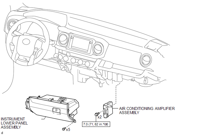
1. INSTALL AIR CONDITIONING AMPLIFIER ASSEMBLY
(a) Install the air conditioner amplifier assembly with the 2 bolts.
Torque:
7.0 N·m {71 kgf·cm, 62 in·lbf}
(b) Connect the 2 connectors.
2. INSTALL INSTRUMENT LOWER PANEL ASSEMBLY
.gif)
3. INSTALL LOWER NO. 2 INSTRUMENT PANEL AIRBAG ASSEMBLY
(See page )
Removal
REMOVAL
PROCEDURE
1. REMOVE LOWER NO. 2 INSTRUMENT PANEL AIRBAG ASSEMBLY
(See page .gif) )
)
2. REMOVE INSTRUMENT LOWER PANEL ASSEMBLY
3. REMOVE AIR CONDITIONING AMPLIFIER ASSEMBLY
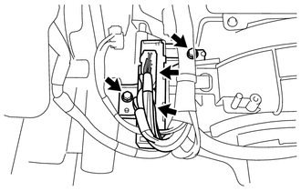
(a) Disconnect the 2 connectors.
(b) Remove the 2 bolts and air conditioning amplifier assembly.
 Air Conditioning
...

Other materials:
Terminals Of Ecu
TERMINALS OF ECU
1. CHECK DRIVER SIDE JUNCTION BLOCK AND MAIN BODY ECU (MULTIPLEX NETWORK BODY
ECU)
(a) Disconnect the MB main body ECU (multiplex network body ECU) connectors.
(b) Measure the voltage and resistance according to the value(s) in the table
below.
HINT:
Measure the values on ...
Open in One Side of Bus 2 Branch Line
DESCRIPTION
When the CAN bus main lines are normal (no open, short to ground, short to +B
or short between lines) and there is an ECU or sensor on the "Communication Bus
Check" screen that is indicated as not communicating or whose connection status
on the "Communication Bus Ch ...
ECU Power Source Circuit
WIRING DIAGRAM
CAUTION / NOTICE / HINT
NOTICE:
Inspect the fuses for circuits related to this system before performing the following
inspection procedure.
PROCEDURE
1.
INSPECT BATTERY
(a) Check the battery voltage.
Standard voltage:
11 to 14 V
NG
...
