DESCRIPTION
In Test Mode (signal check), a malfunction in the speed sensor that cannot be detected when the vehicle is stopped can be detected while driving.
Sensor check mode can be entered by connecting terminals TS and CG of the DLC3 and turning the ignition switch from off to ON.
WIRING DIAGRAM
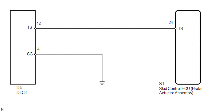
CAUTION / NOTICE / HINT
NOTICE:
When replacing the skid control ECU (brake actuator assembly), perform zero point
calibration and store system information (See page
.gif) ).
).
PROCEDURE
|
1. |
CHECK HARNESS AND CONNECTOR (BRAKE ACTUATOR ASSEMBLY - TS of DLC3) |
(a) Turn the ignition switch off.
(b) Disconnect the S1 skid control ECU (brake actuator assembly) connector.
(c) Measure the resistance according to the value(s) in the table below.
Standard Resistance:
|
Tester Connection |
Condition |
Specified Condition |
|---|---|---|
|
S1-24 (TS) - D4-12 (TS) |
Always |
Below 1 Ω |
|
S1-24 (TS) or D4-12 (TS) - Body ground |
Always |
10 kΩ or higher |
| NG | .gif) |
REPAIR OR REPLACE HARNESS OR CONNECTOR |
|
.gif)
|
2. |
CHECK HARNESS AND CONNECTOR (CG of DLC3 - BODY GROUND) |
|
(a) Measure the resistance according to the value(s) in the table below. Standard Resistance:
|
|
.png)
| OK | |
REPLACE BRAKE ACTUATOR ASSEMBLY |
| NG | |
REPAIR OR REPLACE HARNESS OR CONNECTOR |