DESCRIPTION
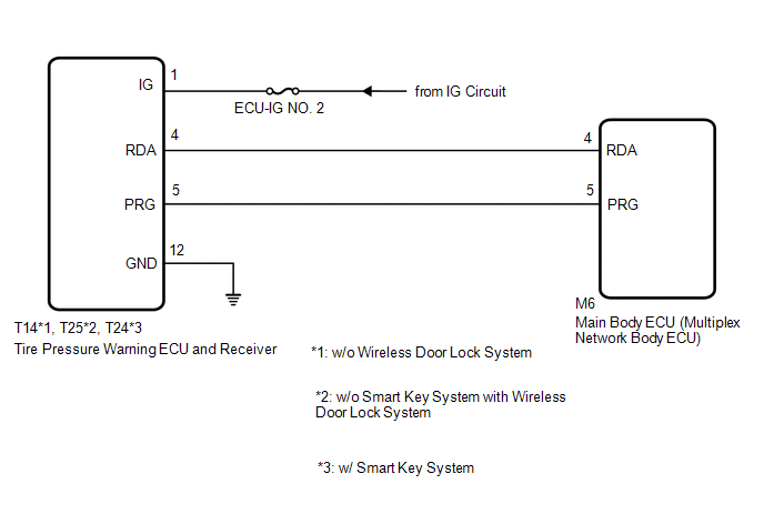
The main body ECU (multiplex network body ECU) and tire pressure warning ECU and receiver are connected using 2 direct lines that they use to communicate with each other.
|
DTC No. |
Detection Item |
DTC Detection Condition |
Trouble Area |
Note |
|---|---|---|---|---|
|
B1247 |
Tire Pressure Monitor Receiver Communication Stop |
In diagnostic mode, an applicable RDA signal cannot be received within 10 seconds after a PRG signal is sent from the main body ECU (multiplex network body ECU). |
|
This DTC is for main body ECU (multiplex network body ECU) |
WIRING DIAGRAM
CAUTION / NOTICE / HINT
NOTICE:
- When replacing the tire pressure warning ECU and receiver, read the transmitter IDs stored in the old ECU using the Techstream and write them down before removal.
- It is necessary to perform initialization (See page
.gif) ) after registration (See page
) of the transmitter IDs into the tire
pressure warning ECU and receiver after the ECU has been replaced.
) after registration (See page
) of the transmitter IDs into the tire
pressure warning ECU and receiver after the ECU has been replaced. - If the main body ECU (multiplex network body ECU) is replaced, refer
to Registration (See page ).*
*: w/ Smart Key System
HINT:
Inspect the fuses for circuits related to this system before performing the following procedure.
PROCEDURE
|
1. |
CHECK HARNESS AND CONNECTOR (MAIN BODY ECU (MULTIPLEX NETWORK BODY ECU) - TIRE PRESSURE WARNING ECU AND RECEIVER) |
(a) Disconnect the T14*1, T25*2, T24*3 tire pressure warning ECU and receiver connector.
(b) Disconnect the M6 main body ECU (multiplex network body ECU) connector.
(c) Measure the resistance according to the value(s) in the table below.
Standard Resistance:
|
Tester Connection |
Condition |
Specified Condition |
|---|---|---|
|
T14-4 (RDA) - M6-4 (RDA)*1 T25-4 (RDA) - M6-4 (RDA)*2 T24-4 (RDA) - M6-4 (RDA)*3 |
Always |
Below 1 Ω |
|
T14-4 (RDA) or M6-4 (RDA) - Body ground*1 T25-4 (RDA) or M6-4 (RDA) - Body ground*2 T24-4 (RDA) or M6-4 (RDA) - Body ground*3 |
Always |
10 kΩ or higher |
- *1: w/o Wireless Door Lock System
- *2: w/o Smart Key System with Wireless Door Lock System
- *3: w/ Smart Key System
| NG | .gif) |
REPAIR OR REPLACE HARNESS OR CONNECTOR |
|
.gif)
|
2. |
CHECK HARNESS AND CONNECTOR (POWER SOURCE OF TIRE PRESSURE WARNING ECU AND RECEIVER) |
|
(a) Measure the resistance according to the value(s) in the table below. Standard Resistance:
|
|
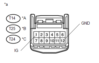
(b) Measure the voltage according to the value(s) in the table below.
Standard Voltage:
|
Tester Connection |
Switch Condition |
Specified Condition |
|---|---|---|
|
T14-1 (IG) - Body ground*1 T25-1 (IG) - Body ground*2 T24-1 (IG) - Body ground*3 |
Ignition switch ON |
10 to 16 V |
|
*a |
Front view of wire harness connector (to Tire Pressure Warning ECU and Receiver) |
- *1: w/o Wireless Door Lock System
- *2: w/o Smart Key System with Wireless Door Lock System
- *3: w/ Smart Key System
| NG | |
REPAIR OR REPLACE HARNESS OR CONNECTOR |
|
|
3. |
REPLACE TIRE PRESSURE WARNING ECU AND RECEIVER |
(a) Replace the tire pressure warning ECU and receiver (See page
).
|
|
4. |
CHECK DTC OUTPUT |
(a) Clear the DTCs (See page ).
(b) Turn the ignition switch off.
(c) Turn the ignition switch to ON.
(d) Check for DTCs (See page ).
OK:
DTC B1247 is not output.
| OK | |
END |
| NG | |
REPLACE MAIN BODY ECU (MULTIPLEX NETWORK BODY ECU) |