TERMINALS OF ECU
1. CLEARANCE WARNING ECU ASSEMBLY

(a) Disconnect the C30 connector from the clearance warning ECU assembly.
(b) Measure the voltage and resistance according to the value(s) in the table below.
|
Terminal No. (Symbol) |
Wiring Color |
Terminal Description |
Condition |
Specified Condition |
|---|---|---|---|---|
|
C30-9 (CLSW) - C30-30 (E) |
Y - W-B |
Back sonar or clearance sonar switch assembly power source signal |
Ignition switch ON, back sonar or clearance sonar switch assembly on |
11 to 14 V |
|
C30-9 (CLSW) - C30-30 (E) |
Y - W-B |
Back sonar or clearance sonar switch assembly power source signal |
Ignition switch ON, back sonar or clearance sonar switch assembly off |
Below 1 V |
|
C30-1 (IG) - C30-30 (E) |
P - W-B |
IG power source signal |
Ignition switch off |
Below 1 V |
|
Ignition switch ON |
11 to 14 V |
|||
|
C30-30 (E) - Body ground |
W-B - Body ground |
Ground |
Always |
Below 1 Ω |
(c) Reconnect the C30 connector to the clearance warning ECU assembly.
(d) Measure the voltage and check for pulses according to the value(s) in the table below.
|
Terminal No. (Symbol) |
Wiring Color |
Terminal Description |
Condition |
Specified Condition |
|---|---|---|---|---|
|
C30-22 (BOR) - C30-30 (E) |
BE - W-B |
Power source for rear sensor circuit |
Ignition switch off |
Below 1 V |
|
Ignition switch ON, back sonar or clearance sonar switch assembly on |
7.2 to 8.8 V |
|||
|
C30-13 (ER) - C30-30 (E) |
R - W-B |
Clearance warning buzzer signal |
Buzzer sounding |
Pulse generation (See waveform 1) |
|
C30-23 (E1) - C30-30 (E) |
B - W-B |
Ground for rear clearance sonar |
Always |
Below 1 V |
|
C30-24 (SOR) - C30-30 (E) |
V - W-B |
Rear sensor communication signal (Rear clearance sonar sensor) |
Ignition switch ON, back sonar or clearance sonar switch assembly on, shift lever in R |
Pulse generation (See waveform 2) |
(e) Using an oscilloscope, check waveform 1.
(1) Waveform 1 (Reference)
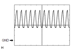
|
Item |
Content |
|---|---|
|
Terminal No. (Symbol) |
C30-13 (ER) - C30-30 (E) |
|
Tool Setting |
2 V/DIV., 500 μsec./DIV. |
|
Vehicle Condition |
When sonar detects obstacle (buzzer sounds) |
|
Buzzer volume |
M2 (Medium volume) |
HINT:
The amplitude of the waveform changes according to the set volume.
(f) Using an oscilloscope, check waveform 2.
(1) Waveform 2 (Reference)
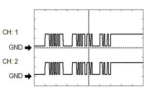
|
Item |
Content |
|---|---|
|
Terminal No. (Symbol) |
C30-24 (SOR) - C30-30 (E) |
|
Tool Setting |
5 V/DIV., 1 msec./DIV. |
|
Condition |
Ignition switch ON, back sonar or clearance sonar switch assembly on, shift lever in R |
HINT:
The waveforms for CH1 and CH2 are same.