TERMINALS OF ECU
1. CHECK 4 WHEEL DRIVE CONTROL ECU
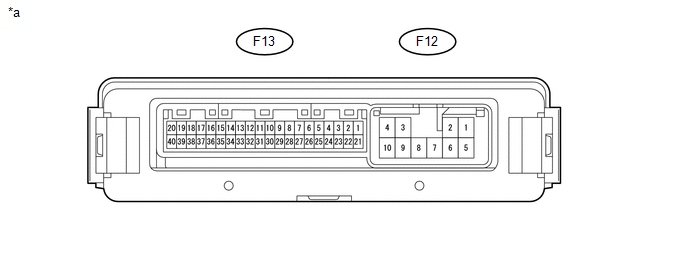 Text in Illustration
|
*a |
Component with harness connected (4 Wheel Drive Control ECU) |
- |
- |
(a) Measure the resistance and voltage according to the value(s) in the table below.
|
Terminal No. (Symbol) |
Wiring Color |
Terminal Description |
Condition |
Specified Condition |
|---|---|---|---|---|
|
F13-12 (SLS) - F12-10 (GND) |
L - W-B |
Differential lock indicator switch |
Ignition switch ON Rear differential FREE |
10 to 14 V |
|
Ignition switch ON Rear differential LOCK |
Below 1.5 V |
|||
|
F13-15 (R) - F12-10 (GND) |
R - W-B |
Differential lock switch input |
Ignition switch ON Differential lock switch not pressed |
11 to 14 V |
|
Ignition switch ON Differential lock switch pressed and held |
Below 1.5 V |
|||
|
F13-20 (CANH) - F13-40 (CANL) |
BE - W |
HIGH-level CAN bus wire - LOW-level CAN bus wire |
Ignition switch off Cable disconnected from negative (-) battery terminal |
54 to 69 Ω |
|
F13-21 (+B) - F12-10 (GND) |
W - W-B |
ECU power supply |
Always |
10 to 14 V |
|
F12-1 (SL+) - F12-10 (GND) |
B - W-B |
Differential lock coil drive output (continuity with IG when operating) |
Ignition switch ON Rear differential free |
Below 1.5 V |
|
Ignition switch ON Switching between free and locked (Condition: A or C) |
Pulse generation (See waveform 1) |
|||
|
Ignition switch ON Rear differential locked (Condition B) |
Pulse generation (See waveform 1) |
|||
|
F12-4 (IG) - F12-10 (GND) |
Y - W-B |
ECU and actuator power supply |
Ignition switch ON |
11 to 14 V |
|
F12-5 (SL-) - F12-10 (GND) |
W - W-B |
Differential lock coil drive output (continuity with GND when operating) |
Ignition switch ON Rear differential free |
Below 1.5 V |
|
Ignition switch ON Rear differential switching between free and locked (Condition: A or C) |
Pulse generation (See waveform 2) |
|||
|
Ignition switch ON Rear differential locked (Condition B) |
Pulse generation (See waveform 2) |
|||
|
F12-10 (GND) - Body ground |
W-B - Body ground |
Ground |
Always |
Below 1 Ω |
(b) Waveform 1
(1) Rear differential in locked condition
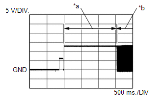
|
Item |
Content |
|---|---|
|
Tester Connection |
F12-1 (SL+) - F12-10 (GND) |
|
Tool Setting |
5 V/DIV., 500 ms./DIV. |
|
Condition: A |
Ignition switch ON Switching between free and locked |
|
Condition: B |
Ignition switch ON Rear differential locked |
|
*a |
Condition: A |
|
*b |
Condition: B |
(2) Rear differential not in locked condition (switching between free and locked)
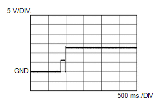
|
Item |
Content |
|---|---|
|
Tester Connection |
F12-1 (SL+) - F12-10 (GND) |
|
Tool Setting |
.5 V/DIV., 500 ms./DIV. |
|
Condition: C |
Ignition switch ON Switching between free and locked |
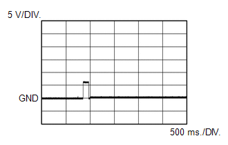
(c) Waveform 2
(1) Rear differential in locked condition
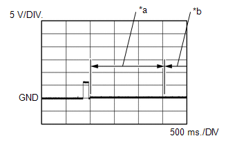
|
Item |
Content |
|---|---|
|
Tester Connection |
F12-5 (SL-) - F12-10 (GND) |
|
Tool Setting |
5 V/DIV., 500 ms./DIV. |
|
Condition: A |
Ignition switch ON Switching between free and locked |
|
Condition: B |
Ignition switch ON Rear differential locked |
|
*a |
Condition: A |
|
*b |
Condition: B |
(2) Rear differential not in locked condition (switching between free and locked)
|
Item |
Content |
|---|---|
|
Tester Connection |
F12-5 (SL-) - F12-10 (GND) |
|
Tool Setting |
5 V/DIV., 500 ms./DIV. |
|
Condition: C |
Ignition switch ON Switching between free and locked |