DESCRIPTION
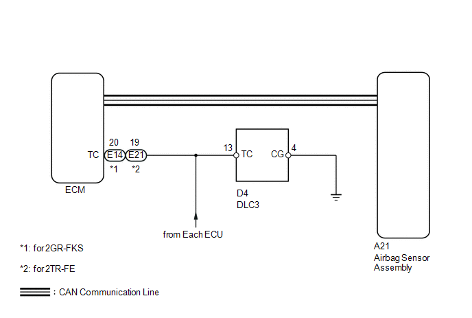
DTC output mode is set by connecting terminals TC and CG of the DLC3.
The DTCs are displayed by blinking the SRS warning light.
HINT:
- Make sure that DTCs which relate to the CAN communication system are
not output. If any of these DTCs are output, check the CAN communication
system (See page
.gif) ).
). - The DTC output mode signal is transmitted through the CAN to an ECU including the airbag sensor assembly. Thus if no systems enter DTC output mode, the ECM may have a malfunction.
- When a warning light keeps blinking, a short to ground in the wiring of terminal TC of the DLC3 or an internal ground short in each ECU is suspected.
WIRING DIAGRAM
PROCEDURE
|
1. |
CHECK HARNESS AND CONNECTOR (DLC3 - ECM) |
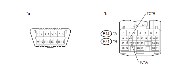 Text in Illustration
|
*A |
for 2GR-FKS |
*B |
for 2TR-FE |
|
*a |
DLC3 |
*b |
Front view of wire harness connector (to ECM) |
(a) Turn the ignition switch off.
(b) Disconnect the connector from the ECM.
(c) Measure the resistance according to the value(s) in the table below.
Standard Resistance:
for 2GR-FKS|
Tester Connection |
Condition |
Specified Condition |
|---|---|---|
|
D4-13 (TC) - E14-20 (TC) |
Always |
Below 1 Ω |
|
Tester Connection |
Condition |
Specified Condition |
|---|---|---|
|
D4-13 (TC) - E21-19 (TC) |
Always |
Below 1 Ω |
| NG | .gif) |
REPAIR OR REPLACE HARNESS, ECU OR CONNECTOR |
|
.gif)
|
2. |
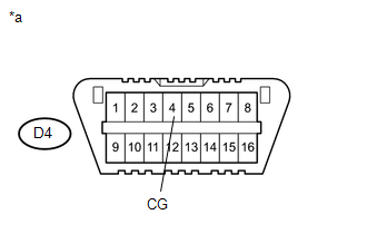
CHECK HARNESS AND CONNECTOR (CG OF DLC3 - BODY GROUND) |
|
(a) Measure the resistance according to the value(s) in the table below. Standard Resistance:
|
|
| NG | |
REPAIR OR REPLACE HARNESS, ECU OR CONNECTOR |
|
|
3. |
CHECK HARNESS AND CONNECTOR (TC CIRCUIT OF ECM) |
(a) Measure the resistance according to the value(s) in the table below.
Standard Resistance:
for 2GR-FKS|
Tester Connection |
Condition |
Specified Condition |
|---|---|---|
|
E14-20 (TC) - Body ground |
Always |
1 MΩ or higher |
|
Tester Connection |
Condition |
Specified Condition |
|---|---|---|
|
E21-19 (TC) - Body ground |
Always |
1 MΩ or higher |
| NG | |
REPAIR OR REPLACE HARNESS, ECU OR CONNECTOR |
|
|
4. |
CHECK DTC |
SST: 09843-18040
|
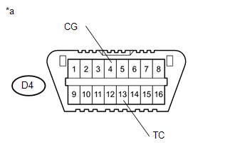
(a) Using SST, connect terminals TC and CG of the DLC3. NOTICE: Connect the terminals to the correct positions to avoid a malfunction. Text in Illustration
|
|
| A | |
USE SIMULATION METHOD TO CHECK |
| B | |
REPLACE ECM |
| C | |
REPLACE ECM |
| D | |
REPLACE AIRBAG SENSOR ASSEMBLY |