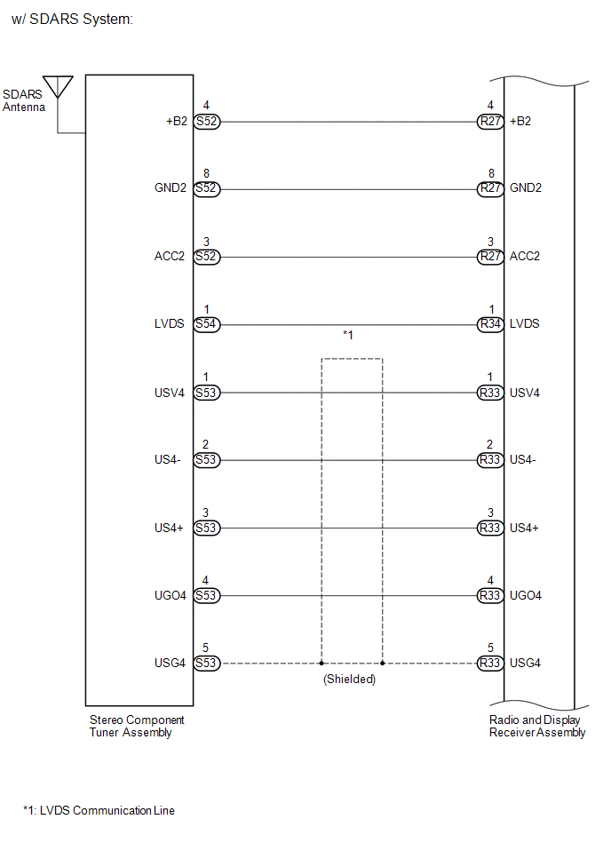
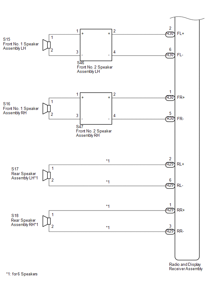
SYSTEM DIAGRAM
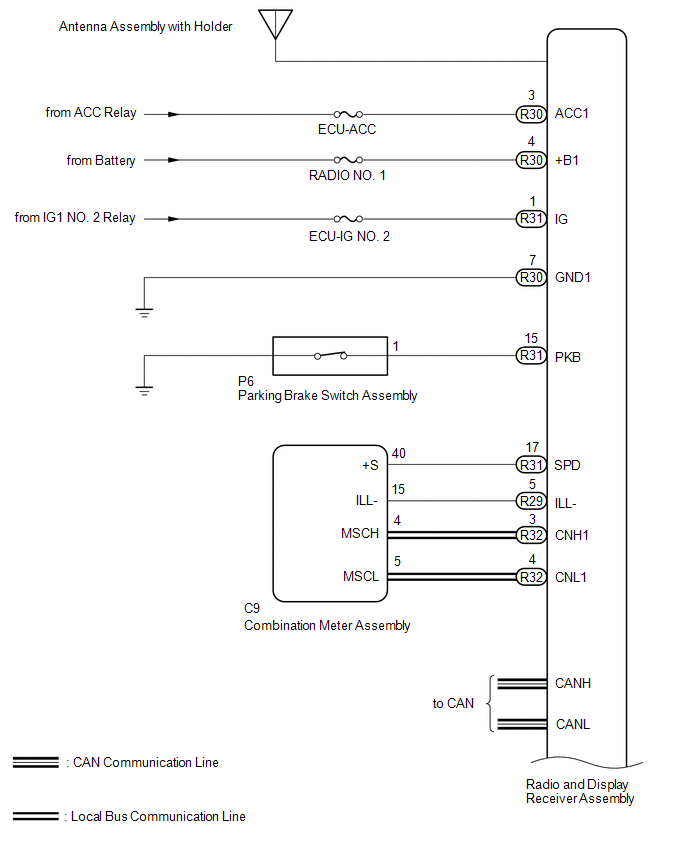
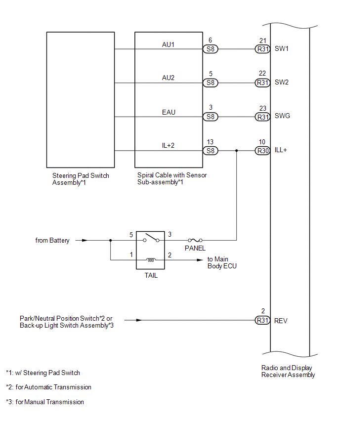
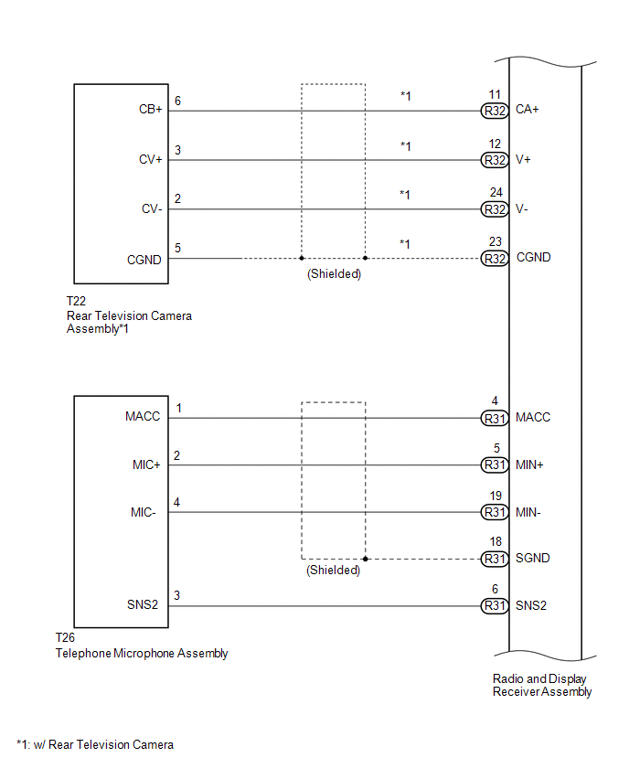
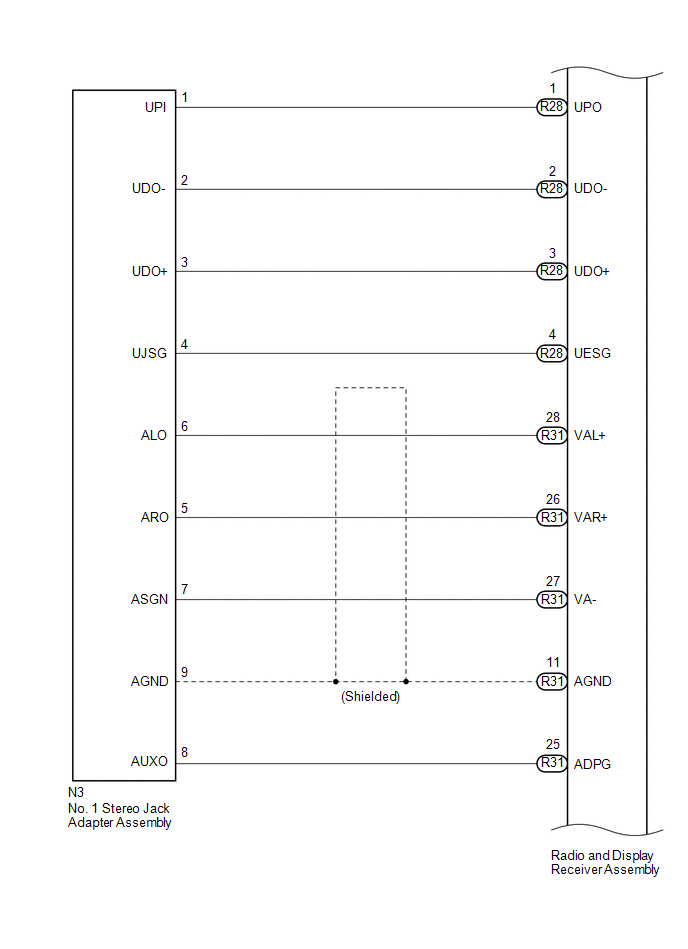
Related Tacoma materials
Inspection
INSPECTION
PROCEDURE
1. INSPECT GENERATOR BRUSH HOLDER ASSEMBLY
(a) Using a vernier caliper, measure the brush length.
Text in Illustration
*a
Length
Standard exposed length:
9.5 ...
On-vehicle Inspection
ON-VEHICLE INSPECTION
PROCEDURE
1. INSPECT RADIATOR CAP SUB-ASSEMBLY
CAUTION:
Do not remove the radiator cap sub-assembly while the engine and radiator assembly
are still hot. Pressurized, hot engine coolant and steam may be released and cause
serious burns.
(a) Measure the valve opening pr ...
Removal
REMOVAL
PROCEDURE
1. REMOVE FUEL TANK ASSEMBLY
Click here
2. DISCONNECT CHARCOAL CANISTER FUEL HOSE
(a) Loosen the hose clip and disconnect the charcoal canister fuel hose.
...