DESCRIPTION
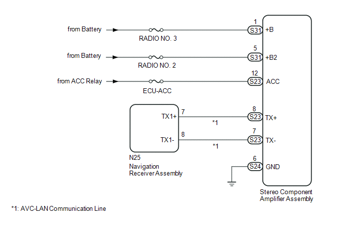
The navigation receiver assembly and stereo component amplifier assembly are connected by the AVC-LAN communication line.
When an AVC-LAN communication error occurs between the navigation receiver assembly and stereo component amplifier assembly, this DTC will be stored.
|
DTC No. |
DTC Detection Condition |
Trouble Area |
|---|---|---|
|
B15D3*1 |
When either condition below is met:
|
|
HINT:
- *1: Even if no fault is present, this DTC may be stored depending on the battery condition or engine start voltage.
- The navigation receiver assembly is the master unit.
WIRING DIAGRAM
CAUTION / NOTICE / HINT
NOTICE:
Inspect the fuses for circuits related to this system before performing the following inspection procedure.
PROCEDURE
|
1. |
CHECK DTC |
(a) If DTC B15C3 is output, perform the troubleshooting of DTC B15C3 first.
Result|
Result |
Proceed to |
|---|---|
|
DTC B15C3 is not output |
A |
|
DTC B15C3 is output |
B |
| B | .gif) |
GO TO DTC "B15C3" IN DIAGNOSTIC TROUBLE CODE CHART |
|
.gif)
|
2. |
CHECK OPTIONAL COMPONENTS (INCLUDING ASSOCIATED WIRING) |
(a) Check that optional components (including associated wiring) which generate radio waves are not installed.
Result|
Result |
Proceed to |
|---|---|
|
Optional components (including associated wiring) are installed. |
A |
|
Optional components (including associated wiring) are not installed. |
B |
HINT:
- Electrical noise from radio waves generated by optional components or the wiring for those components may affect AVC-LAN communication.
- This DTC may be stored when an AVC-LAN communication error occurs due to electrical noise.
| B | |
GO TO STEP 4 |
|
|
3. |
REMOVE OPTIONAL COMPONENTS (INCLUDING ASSOCIATED WIRING) |
(a) Remove optional components (including associated wiring).
NOTICE:
Do not remove optional components or associated wiring without the permission of the customer.
|
|
4. |
CHECK DTC |
(a) Clear the DTCs (See page .gif) ).
).
(b) Recheck for DTCs and check if the same DTC is output again.
OK:
No DTCs are output.
| OK | |
END |
|
|
5. |
CHECK HARNESS AND CONNECTOR (STEREO COMPONENT AMPLIFIER ASSEMBLY POWER SOURCE) |
|
(a) Disconnect the stereo component amplifier assembly connectors. |
|
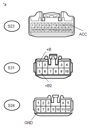
(b) Measure the resistance according to the value(s) in the table below.
Standard Resistance:
|
Tester Connection |
Condition |
Specified Condition |
|---|---|---|
|
S24-6 (GND) - Body ground |
Always |
Below 1 Ω |
(c) Measure the voltage according to the value(s) in the table below.
Standard Voltage:
|
Tester Connection |
Switch Condition |
Specified Condition |
|---|---|---|
|
S31-1 (+B) - S24-6 (GND) |
Always |
11 to 14 V |
|
S31-5 (+B2) - S24-6 (GND) |
Always |
11 to 14 V |
|
S23-12 (ACC) - S24-6 (GND) |
Ignition switch ACC |
11 to 14 V |
|
*a |
Front view of wire harness connector (to Stereo Component Amplifier Assembly) |
| NG | |
REPAIR OR REPLACE HARNESS OR CONNECTOR |
|
|
6. |
CHECK HARNESS AND CONNECTOR (NAVIGATION RECEIVER ASSEMBLY - STEREO COMPONENT AMPLIFIER ASSEMBLY) |
(a) Disconnect the N25 navigation receiver assembly connector.
(b) Disconnect the S23 stereo component amplifier assembly connector.
(c) Measure the resistance according to the value(s) in the table below.
Standard Resistance:
|
Tester Connection |
Condition |
Specified Condition |
|---|---|---|
|
N25-7 (TX1+) - S23-8 (TX+) |
Always |
Below 1 Ω |
|
N25-8 (TX1-) - S23-7 (TX-) |
Always |
Below 1 Ω |
|
N25-7 (TX1+) - Body ground |
Always |
10 kΩ or higher |
|
N25-8 (TX1-) - Body ground |
Always |
10 kΩ or higher |
| NG | |
REPAIR OR REPLACE HARNESS OR CONNECTOR |
|
|
7. |
REPLACE STEREO COMPONENT AMPLIFIER ASSEMBLY |
(a) Replace the stereo component amplifier assembly (See page
).
(b) Clear the DTCs (See page ).
(c) Recheck for DTCs and check if the same DTC is output again.
OK:
No DTCs are output.
| OK | |
END |
| NG | |
REPLACE NAVIGATION RECEIVER ASSEMBLY |