DESCRIPTION
This DTC is stored when the blind spot monitor sensor LH detects a +B short in the blind spot monitor indicator LH.
|
DTC Code |
DTC Detection Condition |
Trouble Area |
|---|---|---|
|
C1AB0 |
With the blind spot monitor main switch assembly (warning canceling switch assembly) on, the voltage applied to the indicator is high for a certain amount of time even though the blind spot monitor sensor is not outputting voltage to the indicator. |
|
WIRING DIAGRAM
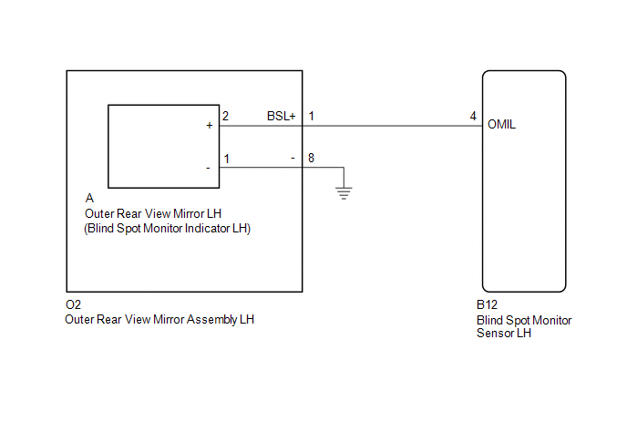
CAUTION / NOTICE / HINT
NOTICE:
When checking for DTCs, make sure that the blind spot monitor main switch assembly (warning canceling switch assembly) is on.
PROCEDURE
|
1. |
CHECK DTC |
(a) Clear the DTCs (See page .gif) ).
).
(b) Recheck for DTCs and check if the same DTC is output again (See page
).
OK:
No DTCs are output.
| OK | .gif) |
USE SIMULATION METHOD TO CHECK |
|
.gif)
|
2. |
CHECK HARNESS AND CONNECTOR (OUTER REAR VIEW MIRROR INDICATOR LH CIRCUIT) |
|
(a) Disconnect the blind spot monitor sensor LH connector. |
|
.png)
(b) Measure the voltage according to the value(s) in the table below.
Standard Voltage:
|
Tester Connection |
Switch Condition |
Specified Condition |
|---|---|---|
|
B12-4 (OMIL) - Body ground |
Ignition switch ON |
Below 1 V |
|
*a |
Front view of wire harness connector (to Blind Spot Monitor Sensor LH) |
| OK | |
REPLACE BLIND SPOT MONITOR SENSOR LH |
|
|
3. |
CHECK HARNESS AND CONNECTOR (BLIND SPOT MONITOR SENSOR LH - OUTER REAR VIEW MIRROR ASSEMBLY LH) |
|
(a) Disconnect the blind spot monitor sensor LH connector. |
|
(b) Disconnect the O2 outer rear view mirror assembly LH connector.
(c) Measure the voltage according to the value(s) in the table below.
Standard Voltage:
|
Tester Connection |
Switch Condition |
Specified Condition |
|---|---|---|
|
B12-4 (OMIL) - Body ground |
Ignition switch ON |
Below 1 V |
|
*a |
Front view of wire harness connector (to Blind Spot Monitor Sensor LH) |
| NG | |
REPAIR OR REPLACE HARNESS OR CONNECTOR |
|
|
4. |
CHECK HARNESS AND CONNECTOR (BLIND SPOT MONITOR SENSOR LH - OUTER REAR VIEW MIRROR LH) |
(a) Reconnect the O2 outer rear view mirror assembly LH connector.
|
(b) Disconnect the blind spot monitor sensor LH connector. |
|
(c) Disconnect the A outer rear view mirror LH connector.
(d) Measure the voltage according to the value(s) in the table below.
Standard Voltage:
|
Tester Connection |
Switch Condition |
Specified Condition |
|---|---|---|
|
B12-4 (OMIL) - Body ground |
Ignition switch ON |
Below 1 V |
|
*a |
Front view of wire harness connector (to Blind Spot Monitor Sensor LH) |
| OK | |
REPLACE OUTER REAR VIEW MIRROR LH |
| NG | |
REPLACE OUTER REAR VIEW MIRROR ASSEMBLY LH |