Toyota Tacoma (2015-2018) Service Manual: Removal
REMOVAL
PROCEDURE
1. DRAIN TRANSFER OIL
.gif)
2. REMOVE FRONT PROPELLER SHAFT ASSEMBLY
3. REMOVE PROPELLER WITH CENTER BEARING SHAFT ASSEMBLY
4. SUPPORT TRANSMISSION ASSEMBLY
5. REMOVE NO. 3 FRAME CROSSMEMBER SUB-ASSEMBLY
6. REMOVE REAR NO. 1 ENGINE MOUNTING INSULATOR
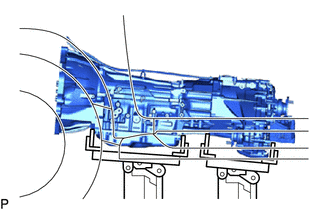
7. SUPPORT TRANSFER ASSEMBLY
(a) Tilt the transmission assembly until the transfer assembly can be removed.
NOTICE:
Do not damage the wire harness, pipe or surrounding parts.
|
(b) Support the transfer assembly with a transmission jack. NOTICE: Secure the transfer assembly to the transmission jack using a belt, etc. to prevent it from falling. |
|
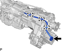
8. DISCONNECT WIRE HARNESS
(a) for 2GR-FKS:
(1) Disconnect the connector.
|
(2) Disengage the 3 clamps to disconnect the wire harness. |
|
(b) for 2TR-FE:
(1) Disconnect the connector.
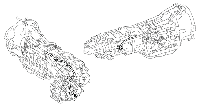
(2) Disengage the 4 clamps to disconnect the wire harness.
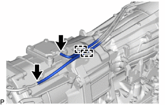
9. DISCONNECT TRANSFER BREATHER HOSE SUB-ASSEMBLY
|
(a) Disconnect the 2 transfer breather hose subassemblies and detach the 2 clamps. |
|
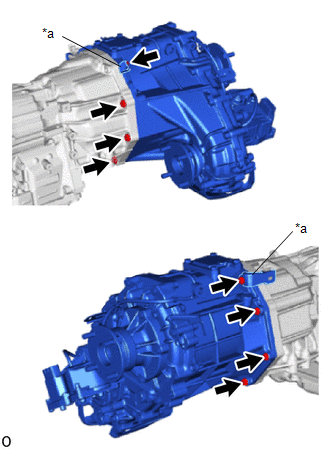
10. REMOVE TRANSFER ASSEMBLY
|
(a) Remove the 8 bolts and 2 clamps. Text in Illustration
|
|
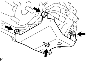
11. REMOVE TRANSFER CASE LOWER PROTECTOR
|
(a) Remove the 4 bolts and transfer case lower protector. |
|
 Components
COMPONENTS
ILLUSTRATION
ILLUSTRATION
ILLUSTRATION
ILLUSTRATION
ILLUSTRATION
ILLUSTRATION
ILLUSTRATION
ILLUSTRATION
ILLUSTRATION
ILLUSTRATION
...
 Installation
INSTALLATION
CAUTION / NOTICE / HINT
CAUTION:
Be sure to perform this procedure with several people as the transfer assembly
is very heavy.
PROCEDURE
1. INSTALL TRANSFER CASE LOWER PROTECTOR
( ...
Other materials:
Inspection
INSPECTION
PROCEDURE
1. INSPECT FRONT SEATBACK HEATER ASSEMBLY
(a) Check the operation of the front seatback heater assembly.
(1) Apply battery voltage and check the operation of the front seatback
heater assembly.
OK:
Connection
Conditio ...
How To Proceed With Troubleshooting
CAUTION / NOTICE / HINT
HINT:
Use these procedures to troubleshoot the combination meter.
*: Use the Techstream.
PROCEDURE
1.
VEHICLE BROUGHT TO WORKSHOP
NEXT
2.
...
Engine Hood Courtesy Switch
Components
COMPONENTS
ILLUSTRATION
Inspection
INSPECTION
PROCEDURE
1. INSPECT HOOD COURTESY SWITCH (HOOD LOCK ASSEMBLY)
(a) Check the resistance.
(1) Measure the resistance according to the value(s) in the table below.
Text in Illustration
*a
...
