SYSTEM DESCRIPTION
The ECM uses the vehicle speed signal and signals from the transmission revolution sensors (NT, SP2) to detect the actual gear (1st, 2nd, 3rd, 4th, 5th or 6th gear).
The ECM compares the actual gear with the shift schedule in the ECM memory to detect mechanical problems of the shift solenoid valves, transmission valve body assembly or automatic transmission assembly (clutch, brake or gear etc.).
|
DTC No. |
DTC Detection Condition |
Trouble Area |
SAE |
|---|---|---|---|
|
P07457F |
Either condition is met (2 trip detection logic):
|
|
P0746 |
MONITOR DESCRIPTION
The ECM commands gear shifts by turning the shift solenoid valves on and off. According to the input turbine speed and output shaft speed, the ECM detects the actual gear (1st, 2nd, 3rd, 4th, 5th or 6th gear). When the gear commanded by the ECM and the actual gear are not the same, the ECM illuminates the MIL and stores the DTC.
MONITOR STRATEGY
|
Related DTCs |
P0746: Shift solenoid valve SL1 OFF malfunction Shift solenoid valve SL1 ON malfunction |
|
Required sensors/Components |
Shift solenoid valve SL1, Transmission revolution sensor (NT), Transmission revolution sensor (SP2), Crankshaft position sensor (NE) |
|
Frequency of operation |
Continuous |
|
Duration |
OFF malfunction: 0.5 sec. ON malfunction: 0.8 sec. |
|
MIL operation |
2 driving cycles |
|
Sequence of operation |
None |
TYPICAL ENABLING CONDITIONS
All:|
The monitor will run whenever the following DTCs are not stored |
P0712, P0713 (TFT (ATF temperature) sensor circuit) P0115, P0117, P0118 (ECT (Engine coolant temperature) sensor circuit) P0717, P07BF, P07C0 (Turbine speed sensor circuit) P0722, P077C, P077D (Output speed sensor circuit) P0335 (Crankshaft position sensor circuit (This condition applies only if using fail-safe)) P0748 (Shift solenoid valve SL1 circuit) P0778 (Shift solenoid valve SL2 circuit) P0798 (Shift solenoid valve SL3 circuit) P2810 (Shift solenoid valve SL4 circuit) P0327, P0328, P0332, P0333 (KCS (Knock control sensor) circuit) P0120, P0121, P0122, P0123, P0220, P0222, P0223, P0604, P0606, P060A, P060B, P060D, P060E, P0657, P1607, P2102, P2103, P2111, P2112, P2118, P2119, P2135 (ETCS (Electronic throttle control system)) U0100 (CAN communication system) |
|
TFT (ATF temperature) sensor circuit |
Not circuit malfunction |
|
ECT (Engine coolant temperature) sensor circuit |
Not circuit malfunction |
|
Turbine speed sensor circuit |
Not circuit malfunction |
|
Output speed sensor circuit |
Not circuit malfunction |
|
Shift solenoid valve SL1 circuit |
Not circuit malfunction |
|
Shift solenoid valve SL2 circuit |
Not circuit malfunction |
|
Shift solenoid valve SL3 circuit |
Not circuit malfunction |
|
Shift solenoid valve SL4 circuit |
Not circuit malfunction |
|
KCS (Knock control sensor) circuit |
Not circuit malfunction |
|
ETCS (Electronic throttle control system) |
Not system down |
|
CAN communication system |
Not system down |
|
Transmission range |
"D" |
|
Duration time from shifting "N" to "D" |
4 sec. or more |
|
TFT (ATF temperature) |
-10°C (14°F) or higher |
|
Engine |
Running |
|
ECM selected gear |
1st, 2nd, 3rd or 4th |
|
Throttle valve opening angle |
3% or more |
|
ECM indicated pressure value of SL1 |
1600 kPa (16.3 kgf/cm2, 232 psi) |
|
ECM selected gear |
5th or 6th |
|
Vehicle speed |
2 km/h (1.2 mph) or more |
|
Throttle valve opening angle |
7.7% or more at engine speed 1600 rpm (Condition varies with engine speed) |
|
ECT (Engine coolant temperature) |
40°C (104°F) or higher |
TYPICAL MALFUNCTION THRESHOLDS
- [OFF malfunction]
|
Turbine speed - Output speed x Gear ratio |
1000 rpm or more |
- [ON malfunction]
- 2 detections are necessary per driving cycle:
- 1st detection: temporary flag ON
- 2nd detection: pending fault code ON
|
Turbine speed / Output speed when output speed less than 1000 rpm |
0.9000 to 1.1000 |
CONFIRMATION DRIVING PATTERN
CAUTION:
When performing the confirmation driving pattern, obey all speed limits and traffic laws.
HINT:
- After repairs have been completed, clear the DTCs and then check that the vehicle has returned to normal by performing the following All Readiness check procedure.
- When clearing the permanent DTCs, refer to the Clear Permanent DTC procedure
(See page
.gif) ).
).
- Connect the Techstream to the DLC3.
- Turn the ignition switch to ON and turn the Techstream on.
- Clear the DTCs (even if no DTCs are stored, perform the clear DTC procedure).
- Turn the ignition switch off and wait for 2 minutes or more.
- Turn the ignition switch to ON and turn the Techstream on.
- Start the engine.
- Perform the D Position Shift Test inspection in Road Test (See page
). [*1]
HINT:
[*1] : Normal judgment procedure.
The normal judgment procedure is used to complete DTC judgment and also used when clearing permanent DTCs.
- Enter the following menus: Powertrain / Transmission / Utility / All Readiness.
- Input the DTC: P07457F.
- Check the DTC judgment result.
Techstream Display
Description
NORMAL
- DTC judgment completed
- System normal
ABNORMAL
- DTC judgment completed
- System abnormal
INCOMPLETE
- DTC judgment not completed
- Perform driving pattern after confirming DTC enabling conditions
N/A
- Unable to perform DTC judgment
- Number of DTCs which do not fulfill DTC preconditions has reached ECU memory limit
HINT:
- If the judgment result shows NORMAL, the system is normal.
- If the judgment result shows ABNORMAL, the system has a malfunction.
- If the judgment result shows INCOMPLETE or N/A, perform the normal judgment procedure again.
CAUTION / NOTICE / HINT
NOTICE:
- Perform the universal trip to clear permanent DTCs (See page
).
- Perform registration and/or initialization when parts related to the
automatic transmission are replaced (See page
).
PROCEDURE
|
1. |
CHECK OTHER DTCS OUTPUT (IN ADDITION TO DTC P07457F) |
(a) Connect the Techstream to the DLC3.
(b) Turn the ignition switch to ON.
(c) Turn the Techstream on.
(d) Enter the following menus: Powertrain / Transmission / Trouble Codes.
(e) Read the DTCs using the Techstream.
Result|
Result |
Proceed to |
|---|---|
|
Only DTC P07457F is output |
A |
|
P07457F and other DTCs are output |
B |
HINT:
If a solenoid is stuck off, DTCs for several solenoids including the malfunctioning solenoid will be detected.
| A | .gif) |
GO TO STEP 3 |
|
.gif)
|
2. |
PERFORM ACTIVE TEST USING TECHSTREAM (CONTROL THE SHIFT POSITION) |
NOTICE:
This test should always be performed with at least 2 people.
(a) Warm up the engine.
(b) Turn the ignition switch off.
(c) Connect the Techstream to the DLC3.
(d) Turn the ignition switch to ON.
(e) Turn the Techstream on.
(f) Enter the following menus: Powertrain / Transmission / Active Test.
(g) According to the display on the Techstream, perform the Active Test.
HINT:
Comparing the gear commanded by the Active Test with the actual gear enables
confirmation of the problem (See page ).
|
Tester Display |
Test Part |
Control Range |
Diagnostic Note |
|---|---|---|---|
|
Control the Shift Position |
Operates the shift solenoid valves to allow gears to be selected manually. |
1st/2nd/3rd/4th/5th/6th Start/Stop |
Can be used to check the operation of the shift solenoid valves. Up-shifts and down-shifts should be performed consecutively. A 10 second interval is required between gear changes. Do not down-shift at high speeds. Doing so will damage the automatic transmission. [Vehicle Condition]
|
HINT:
- This test can be conducted when the vehicle speed is 50 km/h (31 mph) or less.
- The 4th to 5th and 5th to 6th up-shift must be performed with the accelerator pedal released.
- The 6th to 5th and 5th to 4th down-shift must be performed with the accelerator pedal released.
- Do not operate the accelerator pedal for at least 2 seconds after shifting and do not shift successively.
- The gear commanded by the ECM is shown in the Data List / Shift Status display on the Techstream.
(h) Compare the ECM commanded gear and the actual gear.
Result|
Actual Gear during Malfunction |
ECM Commanded Gear |
Proceed to |
||||||
|---|---|---|---|---|---|---|---|---|
|
1st |
2nd |
3rd |
4th |
5th |
6th |
|||
|
Shift solenoid valve SL1 |
Stuck ON |
1st |
2nd |
3rd |
4th |
4th |
4th |
A |
|
Stuck OFF |
N*1 |
N*1 |
N*1 |
N*1 |
5th |
6th |
||
|
Shift solenoid valve SL2 |
Stuck ON |
4th |
4th |
4th |
4th |
5th |
6th |
B |
|
Stuck OFF |
1st |
2nd |
3rd |
1st |
N*1 |
N*1 |
||
|
Shift solenoid valve SL3 |
Stuck ON |
2nd |
2nd |
3rd |
4th |
5th |
6th |
C |
|
Stuck OFF |
1st |
1st |
3rd |
4th |
5th |
N*1 |
||
|
Shift solenoid valve SL4 |
Stuck ON |
3rd |
3rd |
3rd |
4th |
5th |
5th |
D |
|
Stuck OFF |
1st |
2nd |
1st |
4th |
N*1 |
6th |
||
|
Shift solenoid valve SLT |
Stuck ON |
N*2 |
N*2 |
N*2 |
N*2 |
N*2 |
N*2 |
E |
|
Stuck OFF*3 |
1st |
2nd |
3rd |
4th |
5th |
6th |
||
HINT:
- *1: Neutral
- *2: If shift solenoid valve SLT is stuck on, the line pressure will be low. Therefore, the amount of torque that can be transmitted by each gear is lower than the normal limit. When the engine power exceeds this lowered limit, the engine speed will increase freely.
- *3: When shift solenoid valve SLT is stuck off, gear shifting is normal.
| B | |
GO TO DTC CHART (RELATED SHIFT SOLENOID VALVE SL2 PERFORMANCE DTC P07757F) |
| C | |
GO TO DTC CHART (RELATED SHIFT SOLENOID VALVE SL3 PERFORMANCE DTC P07957F) |
| D | |
GO TO DTC CHART (RELATED SHIFT SOLENOID VALVE SL4 PERFORMANCE DTC P28077F) |
| E | |
GO TO DTC CHART (RELATED SHIFT SOLENOID VALVE SLT PERFORMANCE DTC P27137F) |
|
|
3. |
INSPECT SHIFT SOLENOID VALVE SL1 |
|
(a) Remove shift solenoid valve SL1 (See page
|
|
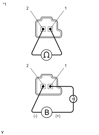
(b) Measure the resistance according to the value(s) in the table below.
Standard Resistance:
|
Tester Connection |
Condition |
Specified Condition |
|---|---|---|
|
1 - 2 |
20°C (68°F) |
5.0 to 5.6 Ω |
(c) Apply 12 V battery voltage to the shift solenoid valve and check that the valve moves and makes an operating noise.
OK:
|
Measurement Condition |
Specified Condition |
|---|---|
|
Valve moves and makes an operating noise |
|
*1 |
Shift Solenoid Valve SL1 |
| NG | |
REPLACE SHIFT SOLENOID VALVE SL1 |
|
|
4. |
INSPECT TRANSMISSION VALVE BODY ASSEMBLY |
(a) Check the transmission valve body assembly (See page
).
OK:
There is no foreign matter on each valve and they operate smoothly.
| OK | |
REPAIR OR REPLACE AUTOMATIC TRANSMISSION ASSEMBLY |
| NG | |
REPAIR OR REPLACE TRANSMISSION VALVE BODY ASSEMBLY |