Toyota Tacoma (2015-2018) Service Manual: Parts Location
PARTS LOCATION
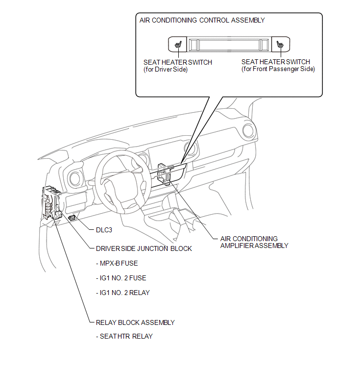
ILLUSTRATION
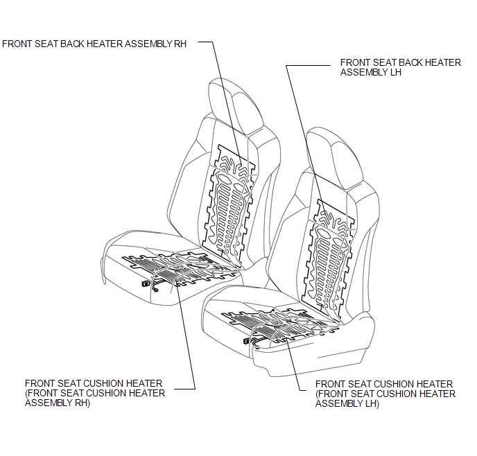
ILLUSTRATION

 Precaution
PRECAUTION
1. EXPRESSIONS OF IGNITION SWITCH
The type of ignition switch used on this model differs depending on the specifications
of the vehicle. The expressions listed in the table below are us ...
Other materials:
Installation
INSTALLATION
CAUTION / NOTICE / HINT
HINT:
Use the same procedures for the RH side and LH side.
The procedures listed below are for the LH side.
When installing a roof drip side moulding clip, heat the vehicle body
and clip using a heat light.
When installing the moulding, ...
Auxiliary boxes
Front
Pull the lid down.
Under the rear seats (Access Cab
models)
Pull up the lever.
Raise the bottom cushion up.
Turn the knob counterclockwise.
Open the lid.
Press the lid against the bottom
of the lower cushion until it is supported by the hookand- loop fastener.
Make sur ...
Brake System (P157800)
DESCRIPTION
This DTC is stored when a malfunction is detected in the vehicle stability control
system.
DTC No.
Detection Item
DTC Detection Condition
Trouble Area
MIL
P157800
Brake System
While the igni ...
