Toyota Tacoma (2015-2018) Service Manual: Outer Mirror Switch
Inspection
INSPECTION
PROCEDURE
1. INSPECT OUTER MIRROR SWITCH ASSEMBLY
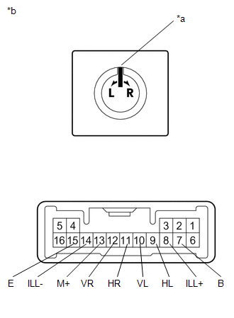
(a) Check the mirror select switch and mirror surface adjust switch.
|
(1) Turn the mirror select switch to the L position. Text in Illustration
|
|
(2) Measure the resistance according to the value(s) in the table below.
Standard Resistance (for left side):
|
Tester Connection |
Condition |
Specified Condition |
|---|---|---|
|
10 (VL) - 7 (B) 13 (M+) - 15 (E) |
Up |
Below 1 Ω |
|
Off |
10 kΩ or higher |
|
|
10 (VL) - 15 (E) 13 (M+) - 7 (B) |
Down |
Below 1 Ω |
|
Off |
10 kΩ or higher |
|
|
9 (HL) - 7 (B) 13 (M+) - 15 (E) |
Left |
Below 1 Ω |
|
Off |
10 kΩ or higher |
|
|
9 (HL) - 15 (E) 13 (M+) - 7 (B) |
Right |
Below 1 Ω |
|
Off |
10 kΩ or higher |
(3) Turn the mirror select switch to the R position.
(4) Measure the resistance according to the value(s) in the table below.
Standard Resistance (for right side):
|
Tester Connection |
Condition |
Specified Condition |
|---|---|---|
|
12 (VR) - 7 (B) 13 (M+) - 15 (E) |
Up |
Below 1 Ω |
|
Off |
10 kΩ or higher |
|
|
12 (VR) - 15 (E) 13 (M+) - 7 (B) |
Down |
Below 1 Ω |
|
Off |
10 kΩ or higher |
|
|
11 (HR) - 7 (B) 13 (M+) - 15 (E) |
Left |
Below 1 Ω |
|
Off |
10 kΩ or higher |
|
|
11 (HR) - 15 (E) 13 (M+) - 7 (B) |
Right |
Below 1 Ω |
|
Off |
10 kΩ or higher |
If the result is not as specified, replace the outer mirror switch assembly.
(b) Check the switch illumination.
(1) Apply battery voltage between the terminals of the light and check the operation of the light.
OK:
|
Measurement Connection |
Specified Condition |
|---|---|
|
Battery positive (+) → Terminal 8 (ILL+) |
Light comes on |
|
Battery negative (-) → Terminal 14 (ILL-) |
If the result is not as specified, replace the outer mirror switch assembly.
 Inner Rear View Mirror
Components
COMPONENTS
ILLUSTRATION
ILLUSTRATION
Calibration
CALIBRATION
1. SELECT COMPASS DISPLAY MODE
(a) The compass switch allows you to select the Display or Non-display mode of
t ...

Other materials:
Theft Deterrent System Communication Line High Fixation (B279A,B279A12)
DESCRIPTION
If the communication line (EFIO-IMI) to the transponder key ECU assembly is stuck
high (e.g. shorted to +B), the ECM stores this DTC.
DTC No.
DTC Detection Condition
Trouble Area
DTC Output Confirmation Operation
B279A*1
...
Steering Angle Sensor Power Source Voltage Malfunction (C1432)
DESCRIPTION
Steering angle sensor (spiral cable with sensor sub-assembly) signals are sent
to the skid control ECU (master cylinder solenoid) via the CAN communication system.
When there is a malfunction in the CAN communication system, it is detected by the
steering angle sensor zero point m ...
Precaution
PRECAUTION
1. CAUTION REGARDING INTERFERENCE WITH ELECTRONIC DEVICES
CAUTION:
People with implantable cardiac pacemakers, cardiac resynchronization
therapy-pacemakers or implantable cardioverter defibrillators should keep
away from the smart key system antennas. The radio waves ma ...
