WIRING DIAGRAM
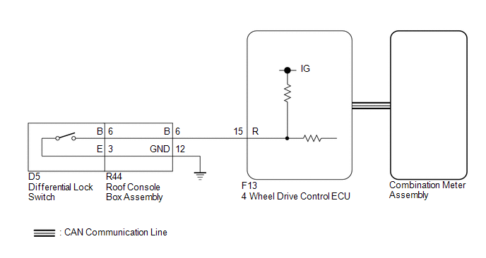
PROCEDURE
|
1. |
CHECK REAR DIFFERENTIAL LOCK INDICATOR LIGHT |
(a) Turn the ignition switch to ON.
(b) for 4WD:
Finish switching to L4.
(c) Check the rear differential lock indicator light.
(d) Press the differential lock switch.
(e) After 60 seconds, check the rear differential lock indicator light.
Result|
Result |
Proceed to |
|---|---|
|
Rear differential lock indicator light blinks or illuminates |
A |
|
Rear differential lock indicator light remains off regardless of switch operation |
B |
|
Rear differential lock indicator light remains illuminated regardless of switch operation |
C |
|
Rear differential lock indicator light rapidly blinks |
D |
- Blinking: Blinks at 0.5 second intervals (0.5 seconds on and 0.5 seconds off)
- Rapidly blinking: Blinks at 0.25 second intervals (0.25 seconds on and 0.25 seconds off)
| A | .gif) |
END |
| C | |
GO TO STEP 8 |
| D | |
GO TO DTC P17CC |
|
.gif)
|
2. |
CHECK CAN COMMUNICATION LINE |
(a) Select "Bus Check" from the System Selection Menu screen, and follow the
prompts on the screen to inspect the CAN Bus (See page
.gif) ).
).
OK:
"Bus Check" indicates no malfunctions in CAN communication.
| NG | |
CHECK CAN COMMUNICATION SYSTEM |
|
|
3. |
READ VALUE USING TECHSTREAM (REAR DIFFERENTIAL LOCK SWITCH CONTROL SW (R)) |
(a) Turn the ignition switch off.
(b) Connect the Techstream to the DLC3.
(c) Turn the Techstream on.
(d) Turn the ignition switch to ON.
(e) Enter the following menus: Powertrain / Four Wheel Drive / Data List.
(f) According to the display on the Techstream, read the Data List.
Four Wheel Drive|
Tester Display |
Measurement Item/Range |
Normal Condition |
Diagnostic Note |
|---|---|---|---|
|
Rear Differential Lock Control SW (R) |
Differential lock switch status (differential lock switch input signal of R terminal on ECU side)/ ON or OFF |
ON: Switch pressed and held OFF: Switch not pressed |
- |
OK:
Display changes according to differential lock switch operation.
| NG | |
GO TO STEP 5 |
|
|
4. |
INSPECT COMBINATION METER ASSEMBLY |
(a) Turn the ignition switch off.
(b) Perform Active Test of the combination meter assembly using the Techstream.
(c) Check the combination meter assembly.
OK:
The rear differential lock indicator light turns on or off in accordance with the Techstream.
| OK | |
REPLACE 4 WHEEL DRIVE CONTROL ECU |
| NG | |
CHECK METER / GAUGE SYSTEM |
|
5. |
INSPECT DIFFERENTIAL LOCK SWITCH |
(a) Disconnect the G13 differential lock switch connector.
|
(b) Measure the resistance according to the value(s) in the table below. Standard Resistance:
|
|
.png)
| NG | |
REPLACE DIFFERENTIAL LOCK SWITCH |
|
|
6. |
INSPECT ROOF CONSOLE BOX ASSEMBLY |
(a) Remove the roof console box assembly.
- for Double Cab: (See page
)
- for Access Cab: (See page
)
.png) Text in Illustration
Text in Illustration
|
*a |
Component without harness connected (Roof Console Box Assembly) |
- |
- |
(b) Measure the resistance according the value(s) in the table below.
Standard Resistance:
|
Tester Connection |
Condition |
Specified Condition |
|---|---|---|
|
R44-6 (B) - 6 (B) |
Always |
Below 1 Ω |
|
R44-12 (GND) - 3 (E) |
Always |
Below 1 Ω |
|
Result |
Proceed to |
|---|---|
|
OK |
A |
|
NG (for Double Cab) |
B |
|
NG (for Access Cab) |
C |
| B | |
REPLACE ROOF CONSOLE BOX ASSEMBLY |
| C | |
REPLACE ROOF CONSOLE BOX ASSEMBLY |
|
|
7. |
CHECK HARNESS AND CONNECTOR (4 WHEEL DRIVE CONTROL ECU - ROOF CONSOLE BOX ASSEMBLY) |
(a) Disconnect the F13 4 wheel drive control ECU connector.
(b) Disconnect the R44 roof console box assembly connector.
(c) Measure the resistance according to the value(s) in the table below.
Standard Resistance:
|
Tester Connection |
Condition |
Specified Condition |
|---|---|---|
|
F13-15 (R) - R44-6 (B) |
Always |
Below 1 Ω |
|
R44-12 (GND) - Body ground |
Always |
Below 1 Ω |
| OK | |
REPLACE 4 WHEEL DRIVE CONTROL ECU |
| NG | |
REPAIR OR REPLACE HARNESS OR CONNECTOR |
|
8. |
CHECK CAN COMMUNICATION LINE |
(a) Select "Bus Check" from the System Selection Menu screen, and follow the
prompts on the screen to inspect the CAN Bus (See page
).
OK:
"Bus Check" indicates no malfunctions in CAN communication.
| NG | |
CHECK CAN COMMUNICATION SYSTEM |
|
|
9. |
READ VALUE USING TECHSTREAM (REAR DIFFERENTIAL LOCK INDICATOR REQUEST) |
(a) Turn the ignition switch off.
(b) Connect the Techstream to the DLC3.
(c) Turn the Techstream on.
(d) Turn the ignition switch to ON.
(e) Enter the following menus: Powertrain / Four Wheel Drive / Data List.
(f) According to the display on the Techstream, read the Data List.
Four Wheel Drive|
Tester Display |
Measurement Item/Range |
Normal Condition |
Diagnostic Note |
|---|---|---|---|
|
Rear Differential Lock Indicator Request |
Rear differential lock indicator light request/ Blink4*, Blink3, Blink2, Blink1, ON or OFF |
|
*: Item not supported, therefore not displayed |
(g) for 4WD:
Finish switching to L4.
(h) Turn the differential lock switch on and off several times and check the Techstream display condition of the rear differential lock indicator light.
Result|
Result |
Proceed to |
|---|---|
|
Data List continues to display ON even when differential lock switch is operated |
A |
|
Data List display changes according to differential lock switch operation |
B |
| A | |
REPLACE 4 WHEEL DRIVE CONTROL ECU |
| B | |
CHECK METER / GAUGE SYSTEM |