Toyota Tacoma (2015-2018) Service Manual: Installation
INSTALLATION
PROCEDURE
1. TEMPORARILY TIGHTEN FRONT SUSPENSION LOWER ARM
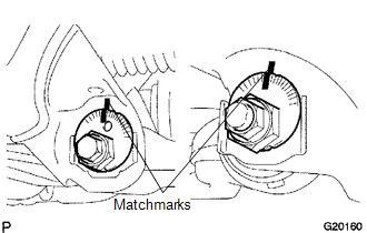
(a) Align the matchmarks on the camber adjust cam No. 2 and toe adjust cam. Temporarily tighten the bolt and the nut.
(b) Install the front lower ball joint attachment, a new nut and a new cotter pin.
Torque:
140 N·m {1428 kgf·cm, 103 ft·lbf}
|
(c) Install the front lower ball joint attachment with the 2 bolts. Torque: 160 N·m {1632 kgf·cm, 118 ft·lbf} |
|
.png)
2. TEMPORARILY TIGHTEN FRONT SHOCK ABSORBER WITH COIL SPRING
.png)
(a) Install the front shock absorber with coil spring, bolt and washer, and temporarily tighten the nut.
3. INSTALL FRONT WHEEL
Torque:
113 N·m {1152 kgf·cm, 83 ft·lbf}
4. STABILIZE FRONT SUSPENSION
(a) Lower the vehicle.
(b) Bounce the vehicle up and down several times to stabilize the suspension.
5. FULLY TIGHTEN FRONT SUSPENSION LOWER ARM
|
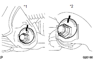
(a) Fully tighten the bolt and nut. Text in Illustration
Torque: for Front Side : 183 N·m {1866 kgf·cm, 135 ft·lbf} for Rear Side : 188 N·m {1917 kgf·cm, 139 ft·lbf} |
|
6. FULLY TIGHTEN FRONT SHOCK ABSORBER WITH COIL SPRING
(a) Fully tighten the nut.
Torque:
83 N·m {846 kgf·cm, 61 ft·lbf}
7. INSPECT AND ADJUST FRONT WHEEL ALIGNMENT
(See page .gif) )
)
 Inspection
INSPECTION
PROCEDURE
1. INSPECT FRONT SUSPENSION LOWER ARM
(a) Flip the ball joint stud back and forth 5 times, as shown in the illustration,
before installing the nut.
(b) Using a torque wren ...
 Reassembly
REASSEMBLY
PROCEDURE
1. INSTALL FRONT LOWER ARM BUSH NO. 1
(a) Install a new lower arm bush using SST, a press and steel plate.
SST: 09631-12090
SST: 09631-32020
NOTICE:
Push the lower arm bu ...
Other materials:
How To Proceed With Troubleshooting
CAUTION / NOTICE / HINT
HINT:
Use these procedures to troubleshoot the smart key system (for Start
Function).
*: Use the Techstream.
PROCEDURE
1.
VEHICLE BROUGHT TO WORKSHOP
NEXT
...
All Doors LOCK/UNLOCK Functions do not Operate Via Door Control Switch or Door
Key Cylinder
DESCRIPTION
The main body ECU (multiplex network body ECU) receives switch signals from the
power window regulator master switch assembly and driver door key cylinder lock
or unlock switch signals from the front door lock assembly. The main body ECU (multiplex
network body ECU) activates the ...
Adjustment
ADJUSTMENT
CAUTION / NOTICE / HINT
HINT:
Centering bolts are used to mount the hood hinge and hood lock assembly.
The hood and hood lock assembly cannot be adjusted with the centering bolts
installed. Substitute the centering bolts with standard bolts when making
adjustments ...
