DESCRIPTION
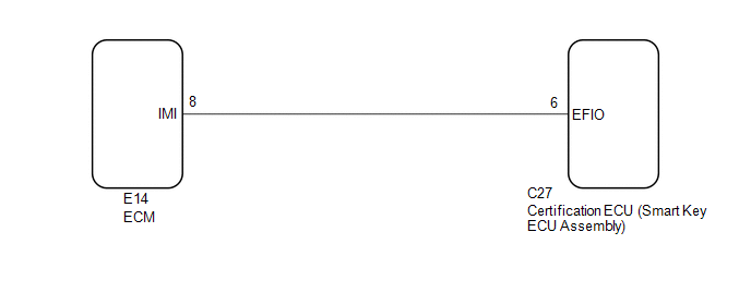
When the communication line (IMI - EFIO) between the ECM and certification ECU (smart key ECU assembly) is stuck high, the ECM stores this DTC.
|
DTC Code |
DTC Detection Condition |
Trouble Area |
DTC Output Confirmation Operation |
|---|---|---|---|
|
B279A12 |
The communication line (IMI - EFIO) between the ECM and certification ECU (smart key ECU assembly) is stuck high (1 trip detection logic*1). |
|
Turn the engine switch on (IG) and wait 6 seconds. |
- *1: Only output while a malfunction is present.
|
Vehicle Condition when Malfunction Detected |
Fail-safe Operation when Malfunction Detected |
|---|---|
|
Engine cannot be started (initial ignition occurs and engine cranks, then ignition stops) |
Engine cannot be started |
|
DTC Code |
Data List and Active Test |
|---|---|
|
B279A12 |
- |
WIRING DIAGRAM
CAUTION / NOTICE / HINT
NOTICE:
- When replacing the certification ECU (smart key ECU assembly), refer
to Registration (See page
.gif) ).
). - After performing repairs, perform the operation that fulfills the DTC output confirmation operation, and then confirm that no DTCs are output again.
HINT:
When DTC B279A12 and the certification ECU (smart key ECU assembly) DTC are output simultaneously, first perform troubleshooting for the certification ECU (smart key ECU assembly) DTC.
PROCEDURE
|
1. |
CLEAR DTC |
(a) Clear the DTCs (See page ).
|
.gif)
|
2. |
CHECK FOR DTC |
(a) Turn the engine switch on (IG) and wait 10 seconds.
(b) Check for DTCs (See page ).
|
Result |
Proceed to |
|---|---|
|
DTC or B279A12 is output |
A |
|
DTC or B279A12 and other DTCs are output |
B |
HINT:
If DTCs other than DTC B279A12 are output, troubleshoot those DTCs first.
| B | .gif) |
GO TO DIAGNOSTIC TROUBLE CODE CHART |
|
|
3. |
CHECK CONNECTION OF CONNECTOR |
(a) Turn the engine switch off.
(b) Check that the connectors are properly connected to the ECM and certification ECU (smart key ECU assembly).
OK:
Connectors are properly connected.
| NG | |
CONNECT CONNECTORS PROPERLY |
|
|
4. |
CHECK HARNESS AND CONNECTOR (CERTIFICATION ECU (SMART KEY ECU ASSEMBLY) - ECM) |
(a) Disconnect the C27 certification ECU (smart key ECU assembly) connector.
(b) Disconnect the E14 ECM connector.
(c) Measure the resistance according to the value(s) in the table below.
Standard Resistance:
|
Tester Connection |
Condition |
Specified Condition |
|---|---|---|
|
C27-6 (EFIO) - E14-8 (IMI) |
Always |
Below 1 Ω |
|
C27-6 (EFIO) or E14-8 (IMI) - Body ground |
Always |
10 kΩ or higher |
| NG | |
REPAIR OR REPLACE HARNESS OR CONNECTOR |
|
|
5. |
REPLACE CERTIFICATION ECU (SMART KEY ECU ASSEMBLY) |
(a) Replace the certification ECU (smart key ECU assembly) with a new one (See
page ).
|
|
6. |
REGISTER RECOGNITION CODES |
(a) Register the key (See page ).
|
|
7. |
REGISTER ECU COMMUNICATION ID |
(a) Register the ECU communication ID (See page
).
|
|
8. |
CLEAR DTC |
(a) Clear the DTCs (See page ).
|
|
9. |
CHECK FOR DTC |
(a) Check for DTCs (See page ).
HINT:
Before checking for DTCs, perform the "DTC Output Confirmation Operation" procedure.
OK:
DTC B279A12 is not output.
| OK | |
END (CERTIFICATION ECU (SMART KEY ECU ASSEMBLY) WAS DEFECTIVE) |
| NG | |
REPLACE ECM |