INSPECTION
PROCEDURE
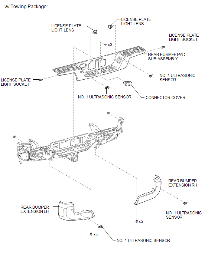
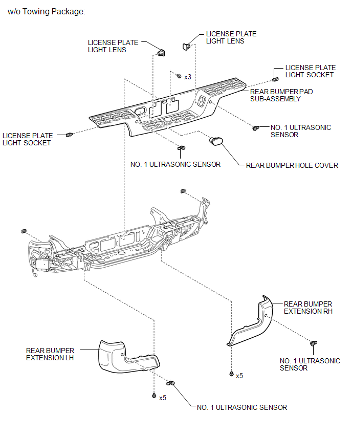
1. INSPECT NO. 1 ULTRASONIC SENSOR
(a) Measure the resistance according to the value(s) in the table below.
Text in Illustration
*a
...
Related Tacoma materials
Transmission Range Sensor Circuit Malfunction (PRNDL Input) (P0705)
DESCRIPTION
The park/neutral position switch detects the shift lever position and sends signals
to the ECM.
DTC No.
DTC Detection Condition
Trouble Area
P0705
One of the following conditions is met:
(A) Any 2 or more of the followin ...
Adjustment
ADJUSTMENT
CAUTION / NOTICE / HINT
HINT:
Centering bolts are used to mount the hood hinge and hood lock assembly.
The hood and hood lock assembly cannot be adjusted with the centering bolts
installed. Substitute the centering bolts with standard bolts when making
adjustments ...
Stop Light Switch OFF Stuck Malfunction (C1426)
DESCRIPTION
The skid control ECU (brake actuator assembly) inputs the stop light signal and
brake operation condition. When the brake pedal is depressed and the stop light
switch signal is not input, C1426 is output.
DTC No.
Detection Item
DTC Detection Conditi ...
 Inspection