Toyota Tacoma (2015-2018) Service Manual: Components
COMPONENTS
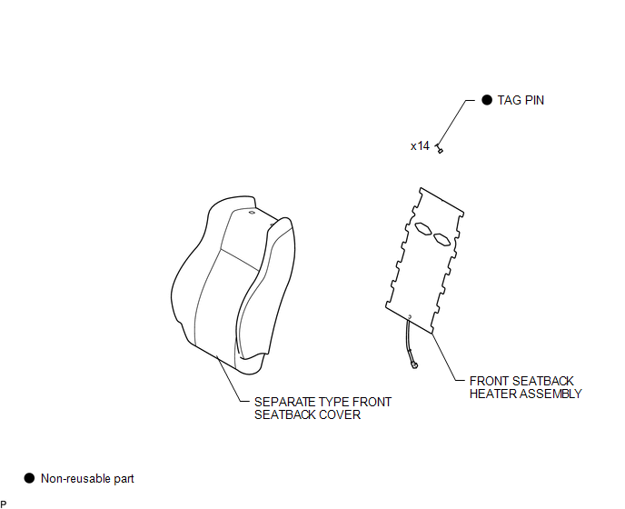
ILLUSTRATION

 Removal
REMOVAL
PROCEDURE
1. REMOVE FRONT SEAT ASSEMBLY (for Driver Side)
(See page
)
2. REMOVE FRONT SEAT ASSEMBLY (for Front Passenger Side)
(See page
)
3. REMOVE SEPARATE TYPE FRONT SEATBACK ...
Other materials:
Brake Switch "A" Circuit Open (P057113)
DESCRIPTION
DTC No.
DTC Detection Condition
Trouble Area
MIL
Note
P057113
Vehicle Condition:
Cruise control operating
Malfunction Status:
Stop light switch assembly circuit malfunction ...
Unlock Warning Switch
Components
COMPONENTS
ILLUSTRATION
Inspection
INSPECTION
PROCEDURE
1. INSPECT UNLOCK WARNING SWITCH ASSEMBLY
(a) Check the resistance.
(1) Measure the resistance according to the value(s) in the table below.
Text in Illustration
*a
Com ...
Installation
INSTALLATION
PROCEDURE
1. SET NO. 1 CYLINDER TO TDC/COMPRESSION
2. INSTALL CAMSHAFT TIMING GEAR BOLT
NOTICE:
There are different types of camshaft timing gear bolts. Make sure to check the
identification mark to determine the tightening torque.
*a
Identification Ma ...
