Components
COMPONENTS
ILLUSTRATION
Installation
INSTALLATION
PROCEDURE
1. INSTALL CLUTCH ACCUMULATOR ASSEMBLY
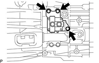
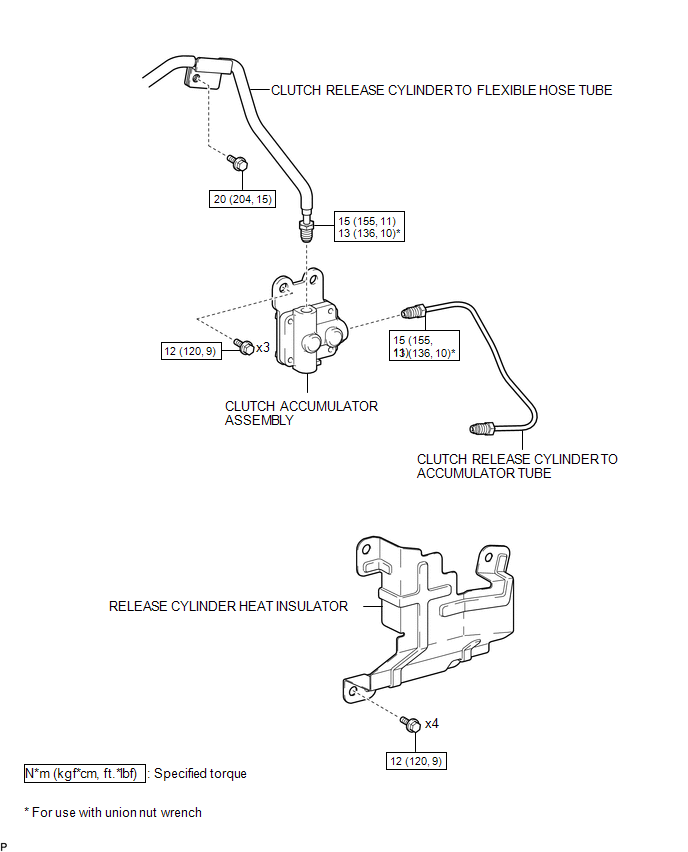
(a) Install the clutch accumulator assembly to the manual transmission assembly with the 3 bolts.
Torque:
12 N·m {120 kgf·cm, 9 ft·lbf}
(b) Using a union nut wrench, connect the clutch release cylinder to flexible hose tube to the clutch accumulator assembly.
Torque:
Specified tightening torque :
15 N·m {155 kgf·cm, 11 ft·lbf}
HINT:
- Calculate the torque wrench reading when changing the fulcrum length
of the torque wrench (See page
.gif) ).
). - When using a union nut wrench (fulcrum length of 22 mm (0.866 in.)) + torque wrench (fulcrum length of 162 mm (6.38 in.)): 13 N*m (136 kgf*cm, 10 ft.*lbf)
(c) Install the clutch release cylinder to flexible hose tube to the manual transmission assembly with the bolt.
Torque:
20 N·m {204 kgf·cm, 15 ft·lbf}
2. INSTALL CLUTCH RELEASE CYLINDER TO ACCUMULATOR TUBE
3. INSTALL RELEASE CYLINDER HEAT INSULATOR
4. INSTALL FRONT PROPELLER SHAFT ASSEMBLY
(See page )
5. FILL RESERVOIR WITH BRAKE FLUID
6. BLEED CLUTCH LINE
7. CHECK FLUID LEVEL IN RESERVOIR
8. INSPECT FOR CLUTCH FLUID LEAK
Removal
REMOVAL
PROCEDURE
1. DRAIN CLUTCH FLUID
2. REMOVE FRONT PROPELLER SHAFT ASSEMBLY
(See page .gif) )
)
3. REMOVE RELEASE CYLINDER HEAT INSULATOR
4. REMOVE CLUTCH RELEASE CYLINDER TO ACCUMULATOR TUBE
5. REMOVE CLUTCH ACCUMULATOR ASSEMBLY
|
(a) Using a union nut wrench, disconnect the clutch release cylinder to flexible hose tube from the clutch accumulator assembly. HINT: Use a container to catch the fluid. |
|
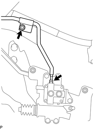
(b) Remove the bolt and separate the clutch release cylinder to flexible hose tube from the manual transmission assembly.
|
(c) Remove the 3 bolts and clutch accumulator assembly from the manual transmission assembly. |
|