Toyota Tacoma (2015-2018) Service Manual: Automatic Transmission Assembly(for 2tr-fe)
Components
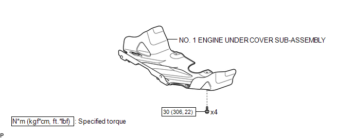
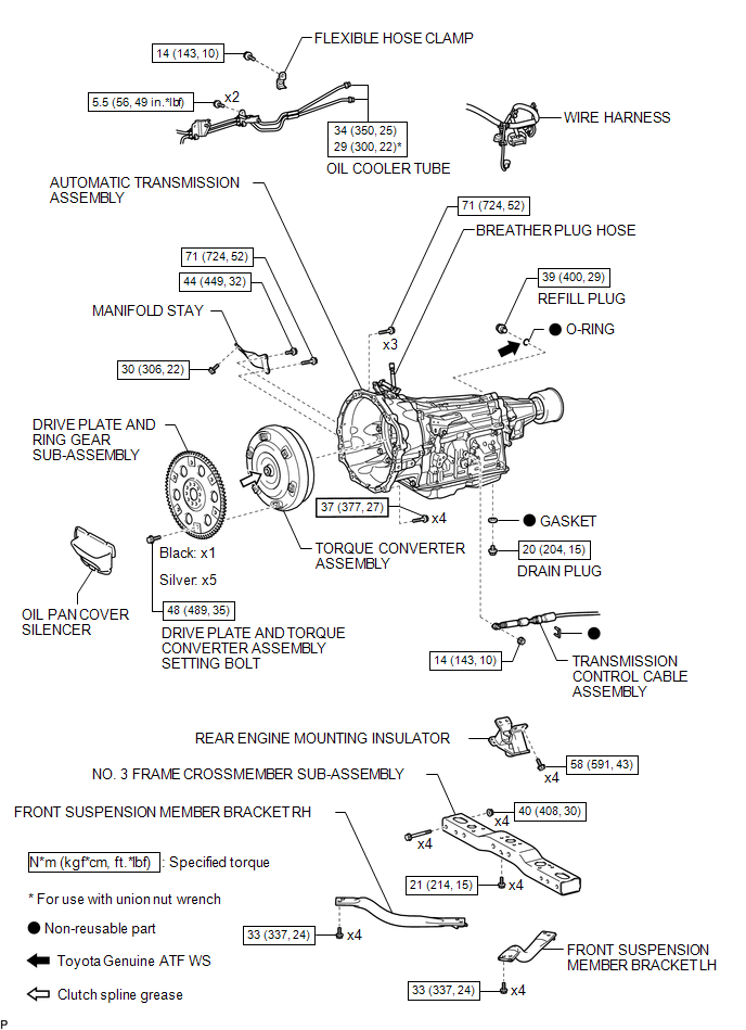
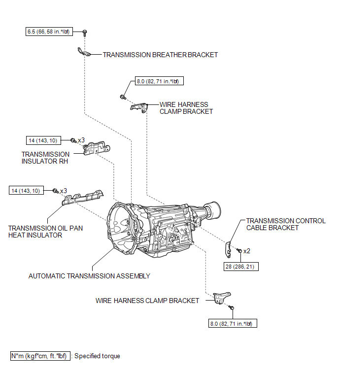
COMPONENTS
ILLUSTRATION
ILLUSTRATION
ILLUSTRATION
 Automatic Transmission Assembly(for 2gr-fks)
Components
COMPONENTS
ILLUSTRATION
ILLUSTRATION
ILLUSTRATION
...

Other materials:
Engine compartment
2.7 L 4-cylinder (2TR-FE) engine
1. Washer fluid tank
2.Radiator cap
3.Engine coolant reservoir
4. Engine oil filler cap
5. Power steering fluid reservoir
6. Engine oil level dipstick
7. Brake fluid reservoir
8. Fuse box
9. Battery
10. Condenser
11. Radiator
4.0 L V6 (1GR-FE) engine
...
Customize Parameters
CUSTOMIZE PARAMETERS
PROCEDURE
1. CUSTOMIZE POWER WINDOW CONTROL SYSTEM
HINT:
The following items can be customized.
NOTICE:
When the customer requests a change in a function, first make sure that
the function can be customized.
Record the current settings before customizing.
...
Diagnosis System
DIAGNOSIS SYSTEM
1. DESCRIPTION
(a) Smart key system (for start function) data and the Diagnostic Trouble Codes
(DTCs) can be read through the Data Link Connector 3 (DLC3) of the vehicle. When
the system seems to be malfunctioning, use the Techstream to check for malfunctions
and perform rep ...
