Even slightly touching the sensor may change the resistance
value. Be sure to hold the sensor connector.
When measuring, the sensor temperature must be the same as the
ambient temperature.
HINT:
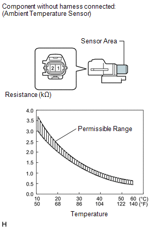
As the temperature increases, the resistance decreases (see the graph).
If the resistance is not as specified, replace the ambient temperature
sensor.
Removal
REMOVAL
PROCEDURE
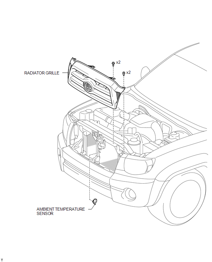
1. REMOVE RADIATOR GRILLE
2. REMOVE AMBIENT TEMPERATURE SENSOR
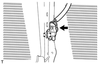
(a) Disengage the harness clamp.
(b) Disconnect the connector and remove the ambient temperature sensor.
Installation
INSTALLATION
PROCEDURE
1. INSTALL AMBIENT TEMPERATURE SENSOR
(a) Engage the harness clamp and install the ambient temperature sensor.
(b) Connect the connector.
2. INSTALL RADIATOR GRILLE
Related Tacoma materials
Power windows*
The power windows can be opened/closed using the following switches.
Driver’s power window switches
Closing
Opening
...
Voice Guidance does not Function
PROCEDURE
1.
CHECK VOICE GUIDANCE SETTING
(a) Check that the voice guidance setting is not off.
OK:
Voice guidance setting is not off.
NG
CHANGE THE VOICE GUIDANCE SETTI ...
Lost Communication with Meter (B1324)
DESCRIPTION
This DTC is stored when a communication error occurs between the navigation receiver
assembly and combination meter assembly.
DTC No.
DTC Detection Condition
Trouble Area
B1324 ...
.gif)
.png)
.gif)