DESCRIPTION
This DTC is stored when a communication error occurs between the navigation receiver assembly and combination meter assembly.
|
DTC No. |
DTC Detection Condition |
Trouble Area |
|---|---|---|
|
B1324 |
After the navigation receiver assembly receives a registration information signal, which is sent by the combination meter assembly when the ignition switch is ACC, 1 or more times, the navigation receiver assembly cannot receive the signal for 30 seconds or more. |
|
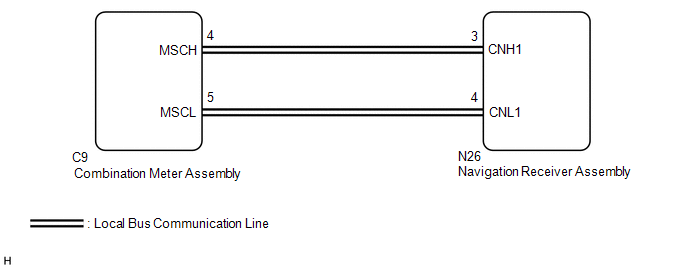
WIRING DIAGRAM
PROCEDURE
|
1. |
CHECK HARNESS AND CONNECTOR (NAVIGATION RECEIVER ASSEMBLY - COMBINATION METER ASSEMBLY) |
(a) Disconnect the N26 navigation receiver assembly connector.
(b) Disconnect the C9 combination meter assembly connector.
(c) Measure the resistance according to the value(s) in the table below.
Standard Resistance:
|
Tester Connection |
Condition |
Specified Condition |
|---|---|---|
|
N26-3 (CNH1) - C9-4 (MSCH) |
Always |
Below 1 Ω |
|
N26-4 (CNL1) - C9-5 (MSCL) |
Always |
Below 1 Ω |
|
N26-3 (CNH1) - Body ground |
Always |
10 kΩ or higher |
|
N26-4 (CNL1) - Body ground |
Always |
10 kΩ or higher |
|
N26-3 (CNH1) - N26-4 (CNL1) |
Always |
10 kΩ or higher |
(d) Measure the voltage according to the value(s) in the table below.
Standard Voltage:
|
Tester Connection |
Condition |
Specified Condition |
|---|---|---|
|
N26-3 (CNH1) - Body ground |
Always |
Below 1 V |
|
N26-4 (CNL1) - Body ground |
Always |
Below 1 V |
| NG | .gif) |
REPAIR OR REPLACE HARNESS OR CONNECTOR |
|
.gif)
|
2. |
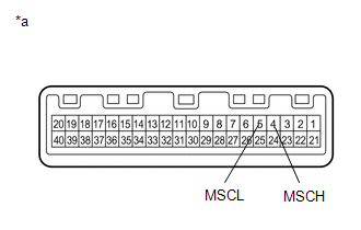
INSPECT COMBINATION METER ASSEMBLY |
(a) Remove the combination meter assembly (See page
.gif) ).
).
|
(b) Measure the resistance according to the value(s) in the table below. Standard Resistance:
|
|
| NG | |
REPLACE COMBINATION METER ASSEMBLY |
|
|
3. |
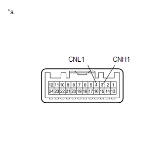
INSPECT NAVIGATION RECEIVER ASSEMBLY |
(a) Remove the navigation receiver assembly (See page
).
|
(b) Measure the resistance according to the value(s) in the table below. Standard Resistance:
|
|
| NG | |
REPLACE NAVIGATION RECEIVER ASSEMBLY |
|
|
4. |
REPLACE COMBINATION METER ASSEMBLY |
(a) Replace the combination meter assembly with a new or known good one (See
page ).
(b) Clear the DTCs (See page ).
(c) Recheck for DTCs and check that no DTCs are output.
OK:
No DTCs are output.
| NG | |
REPLACE NAVIGATION RECEIVER ASSEMBLY |
|
|
5. |
CHECK METER / GAUGE SYSTEM |
(a) Turn the ignition switch to ON and wait 30 seconds.
(b) Operate the steering pad switch assembly and check that the audio tab is displayed on the multi-information display in the combination meter assembly and the audio system can be operated normally.
OK:
Audio system returns to normal.
| OK | |
END |
| NG | |
REPLACE NAVIGATION RECEIVER ASSEMBLY |