Components
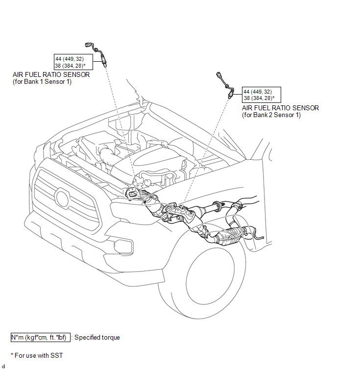
COMPONENTS
ILLUSTRATION
Removal
REMOVAL
PROCEDURE
1. REMOVE AIR FUEL RATIO SENSOR (for Bank 1 Sensor 1)
|
(a) Disconnect the air fuel ratio sensor connector. |
|
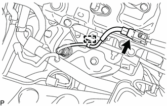
(b) Disengage the clamp to separate the air fuel ratio sensor wire.
|
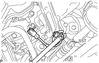
(c) Using SST, remove the air fuel ratio sensor from the exhaust manifold sub-assembly RH. SST: 09224-00011 |
|
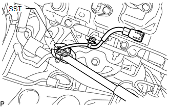
2. REMOVE AIR FUEL RATIO SENSOR (for Bank 2 Sensor 1)
|
(a) Disconnect the air fuel ratio sensor connector. |
|
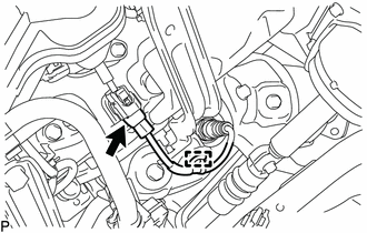
(b) Disengage the clamp to separate the air fuel ratio sensor wire.
|
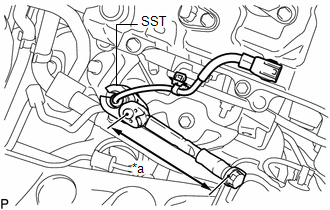
(c) Using SST, remove the air fuel ratio sensor from the exhaust manifold sub-assembly LH. SST: 09224-00011 |
|
Inspection
INSPECTION
PROCEDURE
1. INSPECT AIR FUEL RATIO SENSOR
|
(a) Measure the resistance according to the value(s) in the table below. Text in Illustration
Standard Resistance (for Bank 1 Sensor 1):
Standard Resistance (for Bank 2 Sensor 1):
If the result is not as specified, replace the air fuel ratio sensor. |
|

Installation
INSTALLATION
PROCEDURE
1. INSTALL AIR FUEL RATIO SENSOR (for Bank 1 Sensor 1)
HINT:
Perform "Inspection After Repair" after replacing the air fuel ratio sensor (See
page .gif) ).
).
|
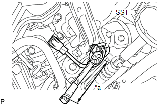
(a) Using SST, install the air fuel ratio sensor to the exhaust manifold sub-assembly RH. Text in Illustration
SST: 09224-00011 Torque: Specified tightening torque : 44 N·m {449 kgf·cm, 32 ft·lbf} HINT:
|
|
(b) Engage the clamp to install the air fuel ratio sensor wire.
(c) Connect the air fuel ratio sensor connector.
2. INSTALL AIR FUEL RATIO SENSOR (for Bank 2 Sensor 1)
HINT:
Perform "Inspection After Repair" after replacing the air fuel ratio sensor (See
page ).
|
(a) Using SST, install the air fuel ratio sensor to the exhaust manifold sub-assembly LH. Text in Illustration
SST: 09224-00011 Torque: Specified tightening torque : 44 N·m {449 kgf·cm, 32 ft·lbf} HINT:
|
|
(b) Engage the clamp to install the air fuel ratio sensor wire.
(c) Connect the air fuel ratio sensor connector.