Toyota Tacoma (2015-2018) Service Manual: Terminals Of Ecu
TERMINALS OF ECU
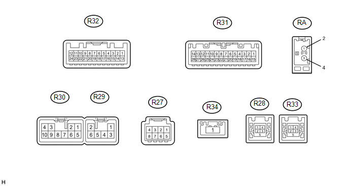
1. RADIO AND DISPLAY RECEIVER ASSEMBLY
|
Terminal No. (Symbol) |
Wiring Color |
Terminal Description |
Condition |
Specified Condition |
|---|---|---|---|---|
|
R30-1 (FR+) - R30-7 (GND1) |
LA-R - W-B |
Sound signal (Front Right) |
Audio system playing |
A waveform synchronized with sounds is output |
|
R30-2 (FL+) - R30-7 (GND1) |
LA-B - W-B |
Sound signal (Front Left) |
Audio system playing |
A waveform synchronized with sounds is output |
|
R30-3 (ACC1) - R30-7 (GND1) |
GR - W-B |
Power source (ACC) |
Ignition switch off |
Below 1 V |
|
Ignition switch ACC |
11 to 14 V |
|||
|
R30-4 (+B1) - R30-7 (GND1) |
W - W-B |
Power source (+B) |
Always |
11 to 14 V |
|
R30-5 (FR-) - R30-7 (GND1) |
LA-G - W-B |
Sound signal (Front Right) |
Audio system playing |
A waveform synchronized with sounds is output |
|
R30-6 (FL-) - R30-7 (GND1) |
LA-W - W-B |
Sound signal (Front Left) |
Audio system playing |
A waveform synchronized with sounds is output |
|
R30-7 (GND1) - Body ground |
W-B - Body ground |
Ground |
Always |
Below 1 V |
|
R30-10 (ILL+) - R30-7 (GND1) |
G - W-B |
Illumination signal |
Light control switch off |
Below 1 V |
|
Light control switch in tail or head position |
11 to 14 V |
|||
|
R29-1 (RR+) - R30-7 (GND1) |
L - W-B |
Sound signal (Rear Right)*2 |
Audio system playing |
A waveform synchronized with sounds is output |
|
R29-2 (RL+) - R30-7 (GND1) |
W - W-B |
Sound signal (Rear Left)*2 |
Audio system playing |
A waveform synchronized with sounds is output |
|
R29-3 (RR-) - R30-7 (GND1) |
LG - W-B |
Sound signal (Rear Right)*2 |
Audio system playing |
A waveform synchronized with sounds is output |
|
R29-5 (ILL-) - R30-7 (GND1) |
BE - W-B |
Illumination (rheostat) signal |
Light control switch off and rheostat switch position medium |
Below 1 V |
|
Light control switch in tail or head position |
Pulse generation |
|||
|
R29-6 (RL-) - R30-7 (GND1) |
B - W-B |
Sound signal (Rear Right)*2 |
Audio system playing |
A waveform synchronized with sounds is output |
|
R31-1 (IG) - R30-7 (GND1) |
LG - W-B |
Power source (IG) |
Ignition switch off |
Below 1 V |
|
Ignition switch ON |
11 to 14 V |
|||
|
R31-2 (REV) - R30-7 (GND1) |
GR - W-B |
Reverse signal |
Ignition switch ON, shift lever not in R |
Below 1 V |
|
Ignition switch ON, shift lever in R |
11 to 14 V |
|||
|
R31-4 (MACC) - R30-7 (GND1) |
R - W-B |
Microphone power supply |
Ignition switch off |
Below 1 V |
|
Ignition switch ON |
4 to 6 V |
|||
|
R31-5 (MIN+) - R30-7 (GND1) |
G - W-B |
Microphone voice signal |
"Bluetooth" hands-free function on |
A waveform synchronized with sounds is output |
|
R31-6 (SNS2) - R30-7 (GND1) |
W - W-B |
Microphone connection detection signal |
Always |
Below 1 V |
|
R31-9 (CANH) |
V |
CAN communication signal |
- |
- |
|
R31-10 (CANL) |
W |
CAN communication signal |
- |
- |
|
R31-11 (AGND) - Body ground |
Shielded - Body ground |
Shield ground |
Always |
Below 1 V |
|
R31-15 (PKB) - R30-7 (GND1) |
Y - W-B |
Parking brake switch signal |
Parking brake switch off |
Below 1 V |
|
Parking brake switch on |
11 to 14 V |
|||
|
R31-18 (SGND) - Body ground |
Shielded - Body ground |
Shield ground |
Always |
Below 1 V |
|
R31-19 (MIN-) - R30-7 (GND1) |
B - W-B |
Microphone voice signal |
"Bluetooth" hands-free function on |
A waveform synchronized with sounds is output |
|
R31-17 (SPD) - R30-7 (GND1) |
V - W-B |
Vehicle Speed signal |
Ignition switch ON Wheel being rotated |
Pulse generation |
|
R31-21 (SW1) - R30-7 (GND1)*1 |
V - W-B |
Steering pad switch signal |
No switch pushed |
2.97 to 3.56 V |
|
Up switch pushed |
0.27 to 0.35 V |
|||
|
Down switch pushed |
0.86 to 1.03 V |
|||
|
Volume+ switch pushed |
1.51 to 1.79 V |
|||
|
Volume- switch pushed |
2.22 to 2.66 V |
|||
|
R31-22 (SW2) - R30-7 (GND1)*1 |
Y - W-B |
Steering pad switch signal |
No switch pushed |
2.97 to 3.56 V |
|
MODE/HOLD switch pushed |
0.27 to 0.35 V |
|||
|
On hook switch pushed |
0.86 to 1.03 V |
|||
|
Off hook switch pushed |
1.51 to 1.79 V |
|||
|
Voice switch pushed |
2.22 to 2.66 V |
|||
|
R31-23 (SWG) - R30-7 (GND1)*1 |
SB - W-B |
Steering pad switch ground |
Always |
Below 1 V |
|
R31-25 (ADPG) - R30-7 (GND1) |
W-B - W-B |
External device connection detection signal |
External device connected |
Below 1 V |
|
R31-26 (VAR+) - R30-7 (GND1) |
W - W-B |
Sound signal (Right) |
External device playing (When stereo jack used) |
A waveform synchronized with sounds is output |
|
R31-27 (VA-) - R30-7 (GND1) |
R - W-B |
Ground |
Always |
Below 1 V |
|
R31-28 (VAL+) - R30-7 (GND1) |
B - W-B |
Sound signal (Left) |
External device playing (When stereo jack used) |
A waveform synchronized with sounds is output |
|
R32-3 (CNH1) |
B |
Local bus communication signal |
- |
- |
|
R32-4 (CNL1) |
W |
Local bus communication signal |
- |
- |
|
R32-24 (V-) - R30-7 (GND1) |
W - W-B |
Ground |
Always |
Below 1 V |
|
R32-12 (V+) - R32-24 (V-) |
R - W |
Video signal |
Ignition switch ON, shift lever in R |
Pulse generation (See waveform 1) |
|
Ignition switch ON, shift lever in R, screen blacked out by covering camera lens |
Pulse generation (See waveform 2) |
|||
|
R32-23 (CGND) - Body ground |
Shield - Body ground |
Shield ground |
Always |
Below 1 V |
|
R32-11 (CA+) - R30-7 (GND1) |
B - W-B |
Power source |
Ignition switch ON, shift lever in R |
5.5 to 7.05 V |
|
R27-3 (ACC2) - R30-7 (GND1)*1 |
Y - W-B |
Power source (ACC) |
Ignition switch off |
Below 1 V |
|
Ignition switch ACC |
11 to 14 V |
|||
|
R27-4 (+B2) - R30-7 (GND1)*1 |
R - W-B |
Power source (+B) |
Always |
11 to 14 V |
|
R27-8 (GND2) - Body ground*1 |
B - Body ground |
Ground |
Always |
Below 1 V |
|
R28-1 (UPO) |
- |
Power source |
- |
- |
|
R28-2 (UDO-) |
- |
Data signal |
- |
- |
|
R28-3 (UDO+) |
- |
Data signal |
- |
- |
|
R28-4 (UESG) |
- |
Ground |
- |
- |
|
R33-2 (US4-)*1 |
- |
Data signal |
- |
- |
|
R33-3 (US4+)*1 |
- |
Data signal |
- |
- |
|
R33-4 (UGO4)*1 |
- |
Ground |
- |
- |
|
R33-5 (USG4)*1 |
- |
Shield ground |
- |
- |
|
R34-1 (LVDS)*1 |
B |
LVDS communication signal |
- |
- |
|
RA-5 (ANT+) - R30-7 (GND1) |
B - W-B |
Power source of antenna |
Ignition switch ACC Radio switch on and AM or FM |
11 to 14 V |
- *1: w/ SDARS System
- *2: for 6 Speakers
(a) Using an oscilloscope, check the waveform.
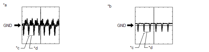
(1) Waveform 1 (Reference)
|
Item |
Content |
|---|---|
|
Terminal No. (Symbol) |
R32-12 (V+) - R32-24 (V-) |
|
Tool Setting |
200 mV/DIV., 50 ÎĽsec./DIV. |
|
Condition |
Ignition switch ON, shift lever in R |
HINT:
The video waveform changes according to the image sent by the rear television camera assembly.
(2) Waveform 2 (Reference)
|
Item |
Content |
|---|---|
|
Terminal No. (Symbol) |
R32-12 (V+) - R32-24 (V-) |
|
Tool Setting |
200 mV/DIV., 50 ÎĽsec./DIV. |
|
Condition |
Ignition switch ON, shift lever in R, screen blacked out by covering camera lens |
HINT:
The video waveform changes according to the image sent by the rear television camera assembly.
Text in Illustration|
*a |
Waveform 1 |
|
*b |
Waveform 2 |
|
*c |
Synchronized Signal |
|
*d |
Video Waveform |
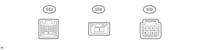
2. STEREO COMPONENT TUNER ASSEMBLY (w/ SDARS System)
|
Terminal No. (Symbol) |
Wiring Color |
Terminal Description |
Condition |
Specified Condition |
|---|---|---|---|---|
|
S52-3 (ACC2) - S52-8 (GND2) |
Y - B |
Power source (ACC) |
Ignition switch off |
Below 1 V |
|
Ignition switch ACC |
11 to 14 V |
|||
|
S52-4 (+B2) - S52-8 (GND2) |
R - B |
Power source (+B) |
Always |
11 to 14 V |
|
S52-8 (GND2) - Body ground |
B - Body ground |
Ground |
Always |
Below 1 V |
|
S53-1 (USV4) |
- |
Power source |
- |
- |
|
S53-2 (US4-) |
- |
Data signal |
- |
- |
|
S53-3 (US4+) |
- |
Data signal |
- |
- |
|
S53-4 (UGO4) |
- |
Ground |
- |
- |
|
S53-5 (USG4) |
B |
Shield ground |
- |
- |
|
S54-1 (LVDS) |
- |
LVDS communication signal |
- |
- |
 Problem Symptoms Table
PROBLEM SYMPTOMS TABLE
NOTICE:
After replacing the stereo component tuner assembly of vehicles subscribed to
pay-type satellite radio broadcasts, XM radio ID registration is necessary (w/ SDARS
...
 Dtc Check / Clear
DTC CHECK / CLEAR
1. CHECK DTC (CHECK USING TECHSTREAM)
(a) Connect the Techstream to the DLC3.
(b) Turn the ignition switch to ON.
(c) Turn the Techstream on.
(d) Enter the following menus: Body ...
Other materials:
Illumination Circuit
DESCRIPTION
Power is supplied to the radio and display receiver assembly and steering pad
switch assembly illumination when the light control switch is in the TAIL or HEAD
position.
WIRING DIAGRAM
CAUTION / NOTICE / HINT
NOTICE:
The vehicle is equipped with a Supplemental Restrain ...
Cellular Phone Inspection
PROCEDURE
1.
CHECK USAGE CONDITION
(a) Check that the vehicle and cellular phone meet the following conditions:
NOTICE:
If changing cellular phone settings, updating software, etc. is necessary, make
sure to obtain the permission of the customer before performin ...
Problem Symptoms Table
PROBLEM SYMPTOMS TABLE
HINT:
Use the table below to help determine the cause of problem symptoms.
If multiple suspected areas are listed, the potential causes of the symptoms
are listed in order of probability in the "Suspected Area" column of the
table. Check each sy ...
