Toyota Tacoma (2015-2018) Service Manual: Terminals Of Ecu
TERMINALS OF ECU
NOTICE:
- DTCs may be output when connectors are disconnected during inspection. Therefore, be sure to clear the DTCs using the Techstream once the inspection has been completed.
- Do not apply excessive force to the f5 forward recognition camera connector.
CHECK FORWARD RECOGNITION CAMERA
(a) Disconnect the forward recognition camera connector.

|
*a |
Front view of wire harness connector (to Forward Recognition Camera) |
- |
- |
(b) Measure the voltage and resistance according to the value(s) in the table below.
|
Terminal No. (Symbol) |
Wiring Color |
Terminal Description |
Condition |
Specified Condition |
|---|---|---|---|---|
|
F46-7 (IGB) - F46-10 (GND) |
BE - W-B |
Power source |
Ignition switch ON |
11 to 14 V |
|
Ignition switch off |
Below 1 V |
|||
|
F46-10 (GND) - Body ground |
W-B - Body ground |
Ground |
Always |
Below 1 Ω |
(c) Reconnect the forward recognition camera connector.

|
*a |
Component with harness connected (Forward Recognition Camera) |
- |
- |
(d) Measure the voltage according to the value(s) in the table below.
|
Terminal No. (Symbol) |
Wiring Color |
Terminal Description |
Condition |
Specified Condition |
|---|---|---|---|---|
|
F46-1 (HTR) - F46-10 (GND) |
R - W-B |
Camera heater (forward recognition hood) operation signal |
Ignition switch ON, camera heater (forward recognition hood) not operating |
11 to 14 V |
|
Ignition switch ON, camera heater (forward recognition hood) operating |
0 to 1.5 V |
|||
|
F46-8 (BZ) - F46-10 (GND) |
L - W-B |
Skid control buzzer |
Ignition switch ON, skid control buzzer not operating |
11 to 14 V |
|
Ignition switch ON, skid control buzzer operating |
0 to 1.5 V |
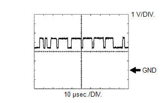
(e) Check for pulses according to the value(s) in the table below.
HINT:
If the waveform is not similar to that shown in the illustration, a malfunction of a CAN bus line, terminating resistor, or the forward recognition camera is suspected.
|
Terminal No. (Symbol) |
Wiring Color |
Terminal Description |
Condition |
Specified Condition |
|---|---|---|---|---|
|
F46-5 (CA1P) - F46-10 (GND) |
L - W-B |
CAN communication signal |
Ignition switch ON |
Pulse generation (See waveform 1) |
|
F46-11 (CA1N) - F46-10 (GND) |
W - W-B |
CAN communication signal |
Ignition switch ON |
Pulse generation (See waveform 2) |
|
F46-6 (CANH) - F46-10 (GND) |
B - W-B |
CAN communication signal |
Ignition switch ON |
Pulse generation (See waveform 1) |
|
F46-12 (CANL) - F46-10 (GND) |
W - W-B |
CAN communication signal |
Ignition switch ON |
Pulse generation (See waveform 2) |
(1) Waveform 1
|
Item |
Content |
|---|---|
|
Terminal Name |
Between F46-5 (CA1P) and F46-10 (GND) Between F46-6 (CANH) and F46-10 (GND) |
|
Tester Range |
1 V/DIV., 10 ÎĽsec./DIV. |
|
Condition |
Ignition switch ON |
HINT:
The waveform varies depending on the CAN communication signal.
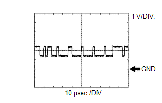
(2) Waveform 2
|
Item |
Content |
|---|---|
|
Terminal Name |
Between F46-11 (CA1N) and F46-10 (GND) Between F46-12 (CANL) and F46-10 (GND) |
|
Tester Range |
1 V/DIV., 10 ÎĽsec./DIV. |
|
Condition |
Ignition switch ON |
HINT:
The waveform varies depending on the CAN communication signal.
 Dtc Check / Clear
DTC CHECK / CLEAR
CHECK DTC
(a) Connect the Techstream to the DLC3.
(b) Turn the ignition switch to ON.
(c) Turn the Techstream on.
(d) Enter the following menus: Chassis / Front Recognition Came ...
 Fail-safe Chart
FAIL-SAFE CHART
FAIL-SAFE FUNCTION
(a) If a malfunction is detected in the forward recognition camera system, the
systems that use the forward recognition camera perform the fail-safe function. ...
Other materials:
Removal
REMOVAL
CAUTION / NOTICE / HINT
NOTICE:
If one of the camshaft timing gear bolts is already removed, do not remove any
other camshaft timing gear bolts.
PROCEDURE
1. REMOVE NO. 2 ENGINE UNDER COVER SUB-ASSEMBLY (w/ Off Road Package)
2. REMOVE NO. 1 ENGINE UNDER COVER SUB-ASSEMBLY
3. REMOVE ...
Front Radar Sensor Incorrect Axial Gap (C1A11)
DESCRIPTION
When the vehicle is determined to be driving in a straight line or on a gradual
curve based on signals from the yaw rate sensor, etc., the millimeter wave radar
sensor assembly performs self diagnosis to check if the sensor beam axis has deviated.
If the millimeter wave radar sens ...
Installation
INSTALLATION
PROCEDURE
1. INSTALL COOLER (ROOM TEMPERATURE SENSOR) THERMISTOR
(a) Connect the cooler air hose.
(b) Connect the connector.
(c) Engage the 2 claws to connect the cooler (room temperature sensor ) thermistor.
2. INSTALL INSTRUMENT PANEL LOWER FINISH PANEL SUB-ASSEMBLY RH
3. I ...
