Toyota Tacoma (2015-2018) Service Manual: Parts Location
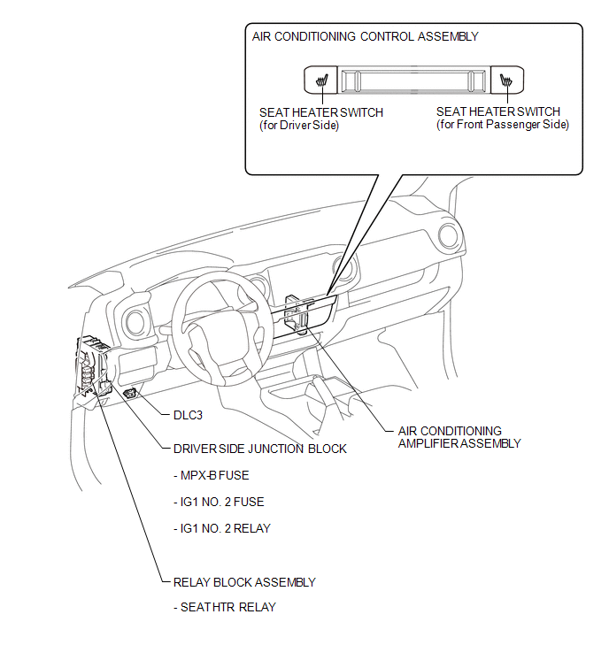
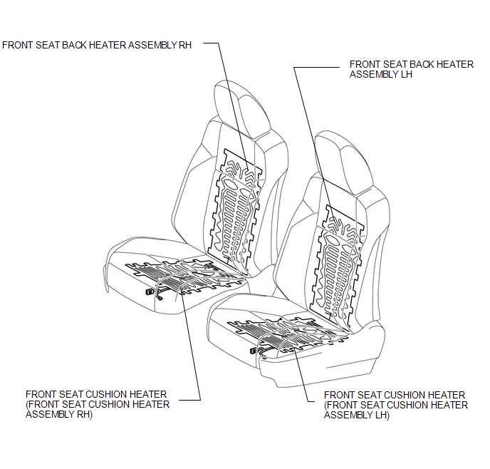
PARTS LOCATION
ILLUSTRATION
ILLUSTRATION

 Precaution
PRECAUTION
1. EXPRESSIONS OF IGNITION SWITCH
The type of ignition switch used on this model differs depending on the specifications
of the vehicle. The expressions listed in the table below are us ...
Other materials:
Disassembly
DISASSEMBLY
PROCEDURE
1. REMOVE PRESSURE RELIEF VALVE
(a) Remove the pressure relief valve and O-ring.
2. REMOVE MAGNET CLUTCH ASSEMBLY
(a) Secure the cooler compressor assembly in a vise between aluminum plates.
(b) Using SST, hold the magnet clutch hub.
SST: 09985-00260
(c) Remove the ...
Diagnostic Trouble Code Chart
DIAGNOSTIC TROUBLE CODE CHART
HINT:
If a trouble code is displayed during the DTC check, inspect the trouble areas
listed for that code. For details of the code, refer to the "See page" below.
Seat Heater System
DTC Code
Detection Item
See page
...
A/C ECU Vehicle Information Reading/Writing Processor Malfunction (B15F5)
DESCRIPTION
This DTC is stored when items controlled by the air conditioning amplifier assembly
cannot be customized via the audio and visual system vehicle customization screen.
HINT:
The air conditioning amplifier assembly controls the air conditioning system
related items that are customiz ...
