Toyota Tacoma (2015-2018) Service Manual: Open in Stop Light Switch Circuit (C1425)
DESCRIPTION
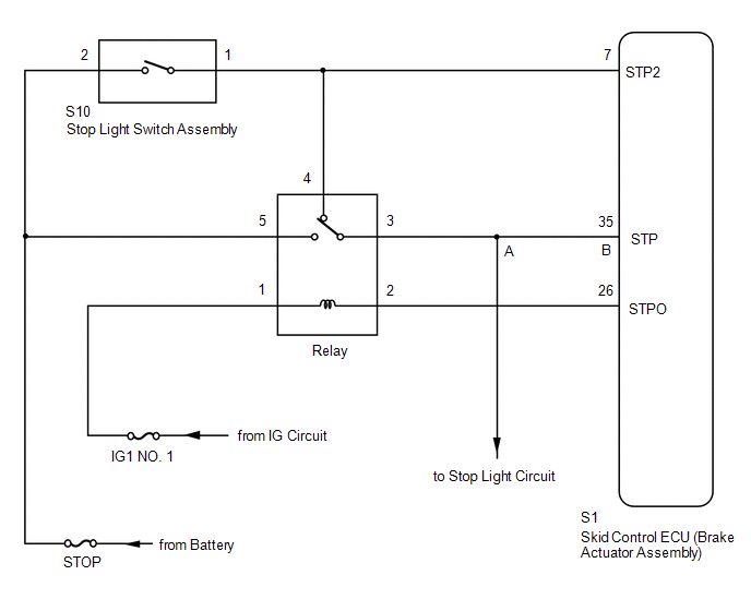
The skid control ECU (brake actuator assembly) detects the brake operating conditions through a signal transmitted by the stop light switch.
The skid control ECU incorporates a circuit to detect an open circuit. This DTC is output when an open circuit is detected in the stop light signal input line.
|
DTC No. |
Detection Item |
DTC Detection Condition |
Trouble Area |
|---|---|---|---|
|
C1425 |
Open in Stop Light Switch Circuit |
When voltage at terminal +BS is 9.5 to 17.4 V, open circuit occurs between STP terminal circuits A and B for 0.3 seconds or more. |
|
WIRING DIAGRAM
CAUTION / NOTICE / HINT
NOTICE:
When replacing the skid control ECU (brake actuator assembly), perform zero point
calibration and store system information (See page
.gif) ).
).
PROCEDURE
|
1. |
CHECK STOP LIGHT OPERATION |
(a) Check that all stop lights come on when the brake pedal is depressed, and go off when the brake pedal is released.
OK:
|
Condition |
Illumination Condition |
|---|---|
|
Brake pedal depressed |
ON |
|
Brake pedal released |
OFF |
| NG | .gif) |
CHECK STOP LIGHT CIRCUIT |
|
.gif)
|
2. |
CHECK HARNESS AND CONNECTOR (STP TERMINAL) |
|
(a) Turn the ignition switch off. |
|
.png)
(b) Make sure that there is no looseness at the locking part and the connecting part of the connectors.
(c) Disconnect the S1 skid control ECU (brake actuator assembly) connector.
(d) Measure the voltage according to the value(s) in the table below.
Standard Voltage:
|
Tester Connection |
Switch Condition |
Specified Condition |
|---|---|---|
|
S1-35 (STP) - Body ground |
Stop light switch assembly on (Brake pedal depressed) |
8 to 14 V |
|
Stop light switch assembly off (Brake pedal released) |
Below 1.5 V |
|
*a |
Front view of wire harness connector (to Skid Control ECU [Brake Actuator Assembly]) |
| NG | |
REPAIR OR REPLACE HARNESS OR CONNECTOR (BRAKE ACTUATOR ASSEMBLY - STOP LIGHT CIRCUIT) |
|
|
3. |
RECONFIRM DTC |
(a) Reconnect the S1 skid control ECU (brake actuator assembly) connector.
(b) Clear the DTCs (See page
).
(c) Turn the ignition switch off.
(d) Start the engine.
(e) Depress the brake pedal several times to test the stop light circuit.
(f) Check if the same DTC is recorded (See page
).
HINT:
If troubleshooting has been carried out according to the Problem Symptoms Table,
refer back to the table and proceed to the next step (See page
).
|
Result |
Proceed to |
|---|---|
|
DTC C1425 is not output |
A |
|
DTC C1425 is output |
B |
| A | |
USE SIMULATION METHOD TO CHECK |
| B | |
REPLACE BRAKE ACTUATOR ASSEMBLY |
 Master Cylinder Pressure Sensor Zero Point High Malfunction (C1422)
DESCRIPTION
DTC No.
Detection Item
DTC Detection Condition
Trouble Area
C1422
Master Cylinder Pressure Sensor Zero Point High M ...
 Stop Light Switch OFF Stuck Malfunction (C1426)
DESCRIPTION
The skid control ECU (brake actuator assembly) inputs the stop light signal and
brake operation condition. When the brake pedal is depressed and the stop light
switch signal is not in ...
Other materials:
ABS Warning Light Remains ON
DESCRIPTION
The skid control ECU (brake actuator assembly) is connected to the combination
meter assembly via CAN communication.
If any of the following is detected, the ABS warning light remains on:
The skid control ECU (brake actuator assembly) connectors are disconnected
from the ...
Removal
REMOVAL
CAUTION / NOTICE / HINT
HINT:
Use the same procedure for the RH side and LH side.
The procedure listed below is for the LH side.
PROCEDURE
1. REMOVE FRONT WHEEL
2. REMOVE NO. 1 ENGINE UNDER COVER SUB-ASSEMBLY
3. SEPARATE FRONT STABILIZER LINK ASSEMBLY LH
...
Portable Player cannot be Registered
CAUTION / NOTICE / HINT
HINT:
Some versions of "Bluetooth" compatible audio players may not function, or the
function may be limited using the navigation receiver assembly, even if the portable
audio player itself can play files (See page ).
PROCEDURE
1.
CHE ...
