Toyota Tacoma (2015-2018) Service Manual: Disassembly
DISASSEMBLY
PROCEDURE
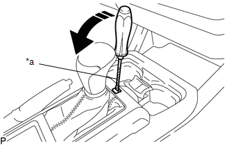
1. REMOVE SHIFT LOCK RELEASE BUTTON COVER
(a) Using a screwdriver with its tip wrapped in protective tape, detach the 2 claws to remove the shift lock release button cover from the console upper panel sub-assembly.
 Text in Illustration
|
*a |
Protective Tape |
 |
Remove in this Direction |
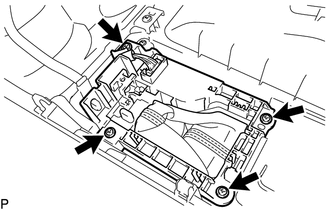
2. REMOVE SHIFT POSITION INDICATOR
|
(a) Remove the 4 screws and shift position indicator from the console upper panel sub-assembly. |
|
3. REMOVE INDICATOR LIGHT WIRE SUB-ASSEMBLY
|
(a) Detach the clamp to separate the indicator light wire sub-assembly from the shift position indicator. |
|
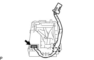
(b) Disconnect the connector to remove the indicator light wire sub-assembly from the shift position indicator.
 Components
COMPONENTS
ILLUSTRATION
...
 On-vehicle Inspection
ON-VEHICLE INSPECTION
PROCEDURE
1. INSPECT SHIFT LEVER POSITION
(a) When moving the shift lever from P to each position with the ignition switch
ON and the brake pedal depressed, check that the s ...
Other materials:
Cargo Light
Components
COMPONENTS
ILLUSTRATION
Removal
REMOVAL
PROCEDURE
1. REMOVE ROOF HEADLINING ASSEMBLY
for Double Cab:
(See page
)
for Access Cab:
(See page
)
2. REMOVE CARGO LIGHT ASSEMBLY (CENTER STOP LIGHT ASSEMBLY)
(a) Remove the 2 nuts.
...
Front Camera Module Circuit (C1AA0)
DESCRIPTION
When an internal malfunction is detected in the forward recognition camera, DTC
C1AA0 is stored.
DTC No.
Detection Item
DTC Detection Condition
Trouble Area
C1AA0
Front Camera Module Circuit
3 seconds ...
Disassembly
DISASSEMBLY
PROCEDURE
1. FIX VANE PUMP ASSEMBLY
(a) Using SST, fix the vane pump assembly in a vise.
SST: 09630-00014
09631-00132
NOTICE:
When using a vise, do not overtighten it.
2. REMOVE POWER STEERING SUCTION PORT UNION
...
