Toyota Tacoma (2015-2018) Service Manual: Components
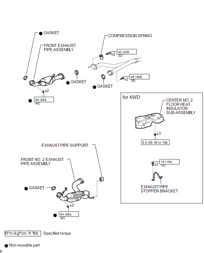
COMPONENTS
ILLUSTRATION
ILLUSTRATION
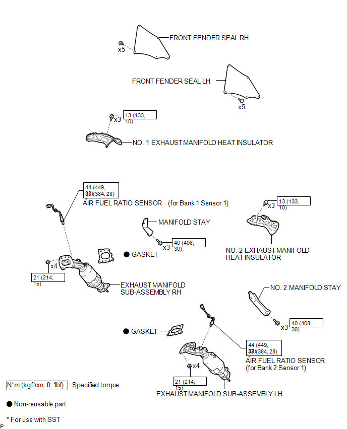
 Exhaust Manifold
...
 Installation
INSTALLATION
PROCEDURE
1. INSTALL EXHAUST MANIFOLD SUB-ASSEMBLY LH
(a) Install a new gasket to the cylinder head LH.
NOTICE:
Be careful of the installation direction.
(b) Temporarily install the ...
Other materials:
Short in Side Squib RH Circuit (B1820/55-B1823/55)
DESCRIPTION
The side squib RH circuit consists of the airbag sensor assembly and the front
seat airbag assembly RH.
The circuit signals the SRS to deploy when airbag deployment conditions are met.
These DTCs are set when a malfunction is detected in the side squib RH circuit.
DTC No ...
Lost Communication with Brake System Control Module (U0129/29)
DESCRIPTION
The tire pressure warning ECU and receiver receives signals from the skid control
ECU (brake actuator assembly) via the CAN communication system.
DTC No.
DTC Detection Condition
Trouble Area
U0129/29
Lost communication with ...
Reassembly
REASSEMBLY
PROCEDURE
1. INSTALL BRAKE BOOSTER ACCUMULATOR ASSEMBLY
(a) Place the brake booster pump in a vise with a cloth.
(b) Install the brake booster accumulator pipe, compression spring and a new
O-ring.
NOTICE:
Ensure that no foreign matter enters the pump.
(c) Using a socket wrench ...
