Toyota Tacoma (2015-2018) Service Manual: CD Sound Skips
PROCEDURE
|
1. |
CHECK CD |
|
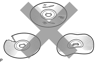
(a) Check that the CD is not deformed or cracked. OK: No deformation or cracks on the CD |
|
| NG | .gif) |
CD IS FAULTY |
|
.gif)
|
2. |
CHECK CD |
|
(a) Check the CD. OK: The CD is clean. NOTICE: Do not use a conventional record cleaner or anti-static preservative. HINT: If dirt is on the CD surface, wipe it clean with a soft cloth from the inside to the outside in a radial direction. |
|
.png)
| NG | |
CLEAN CD |
|
|
3. |
REPLACE CD AND RECHECK |
(a) Replace the CD with a known good one and check that the malfunction disappears.
OK:
Malfunction disappears.
| OK | |
CD WAS FAULTY |
|
|
4. |
CHECK RADIO AND DISPLAY RECEIVER ASSEMBLY |
(a) Check the radio and display receiver assembly installation condition.
(1) Check that the radio and display receiver assembly is properly installed.
OK:
The radio and display receiver assembly is properly installed.
| OK | |
REPLACE RADIO AND DISPLAY RECEIVER ASSEMBLY |
| NG | |
REINSTALL RADIO AND DISPLAY RECEIVER ASSEMBLY PROPERLY |
 CD cannot be Inserted / Played or CD is Ejected Right After Insertion
PROCEDURE
1.
CHECK IF A PROPER CD IS INSERTED
(a) Make sure that the CD is an audio CD or a CD with an MP3, WMA or AAC file,
and that it is not deformed, flawed, st ...
 Radio Broadcast cannot be Received or Poor Reception
PROCEDURE
1.
CHECK RADIO AND DISPLAY RECEIVER ASSEMBLY
(a) Check the radio automatic station search function.
(1) Check the radio automatic station search function b ...
Other materials:
System Diagram
SYSTEM DIAGRAM
Transmitting ECU (Transmitter)
Receiving ECU
Signals
Communication Method
ECM
Skid control ECU
Throttle position signal
Engine speed signal
Accelerator pedal position ...
Terminals Of Ecm
TERMINALS OF ECM
1. CHECK ECM
HINT:
The standard normal voltage between each pair of ECM terminals is shown in the
table below. The appropriate conditions for checking each pair of terminals are
also indicated. The result of checks should be compared with the standard normal
voltage for t ...
Door Courtesy Switch Circuit
DESCRIPTION
The main body ECU (multiplex network Body ECU) receives a door open or closed
signal from each door courtesy light switch.
WIRING DIAGRAM
CAUTION / NOTICE / HINT
NOTICE:
Recognition code registration is necessary when replacing the main body
ECU (multiplex network bo ...
