
Toyota Tacoma (2015-2018) Service Manual: Brake Fluid(for Hydraulic Brake Booster)
On-vehicle Inspection
ON-VEHICLE INSPECTION
PROCEDURE
1. INSPECT FLUID LEVEL IN RESERVOIR
|
(a) Turn the ignition switch to OFF, and depress the brake pedal more than 40 times (until the pedal reaction feels light and pedal stroke becomes longer), and adjust the fluid level to the MAX level. |
|
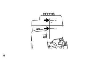
(b) When the ignition switch is turned to the ON, brake fluid is sent to the accumulator and the fluid level decreases by approximately 5 mm from the level when the ignition switch is off (normal).
Fluid:
SAE J1703 or FMVSS No. 116 DOT 3
Replacement
REPLACEMENT
CAUTION / NOTICE / HINT
NOTICE:
- Immediately wash off any brake fluid that comes into contact with any painted surfaces.
- Depressing the brake pedal with the reservoir cap removed will cause the fluid to spray.
HINT:
- If any work is done on the brake system or if air in the brake lines is suspected, bleed the air from the system.
- When bleeding, maintain the amount of fluid in the reservoir between the Min. and Max. lines.
PROCEDURE
1. FILL RESERVOIR WITH BRAKE FLUID
Fluid:
SAE J1703 or FMVSS NO. 116 DOT3
2. BLEED BRAKE BOOSTER WITH ACCUMULATOR PUMP ASSEMBLY
HINT:
If the brake master cylinder is disassembled, the brake line is disconnected from the brake master cylinder or if the reservoir becomes empty, bleed the brake master cylinder.
(a) Turn the ignition switch to ON, and wait until the pump motor has stopped (step A).
HINT:
Pump operating sound can be heard.
(b) Turn the ignition switch to OFF, and depress the brake pedal more than 20 times (step B).
HINT:
When pressure in the accumulator is released, the reaction force becomes lighter and the stroke becomes longer.
(c) Repeat step A and B 5 times (step C).
(d) Turn the ignition switch to ON, and check that the pump stops after approximately 8 to 14 seconds.
NOTICE:
If the pump does not stop, repeat step C again.
3. BLEED BRAKE LINE
(a) Turn the ignition switch to ON, and wait until the pump motor has stopped.
HINT:
Pump operating sound can be heard.
|
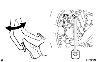
(b) Front brake line. (1) Connect the vinyl tube to the brake caliper. (2) Depress the brake pedal several times, then loosen the bleeder plug with the pedal held down (step D). (3) At the point when the fluid stops coming out, tighten the bleeder plug, then release the brake pedal (step E). (4) Repeat step D and E until all the air in the fluid has been bled out. Torque: 11 N·m {110 kgf·cm, 8 ft·lbf} (5) Repeat the above procedures to bleed the other brake line. |
|
|
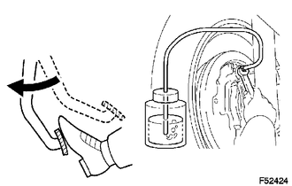
(c) Rear brake line. (1) Connect the vinyl tube to the wheel cylinder. (2) Depress the brake pedal, hold it, and then loosen the bleeder plug. HINT: Brake fluid is pumped out automatically. (3) Loosen the bleeder plug and release air. NOTICE: Keep brake fluid in the reservoir tank above the MIN line during the above procedures. (4) When the air is completely bled out of the brake fluid through the bleeder plug, tighten the bleeder plug. Torque: 11 N·m {110 kgf·cm, 8 ft·lbf} (5) Repeat the above procedures to bleed the other brake line. |
|
4. BLEED MASTER CYLINDER SOLENOID
HINT:
If the brake master cylinder is disassembled, the brake line is disconnected from the brake master cylinder or if the reservoir become empty, bleed the brake master cylinder.
(a) Connect the Techstream to the DLC3.
(b) Turn the ignition switch to ON.
(c) Select "Active Test" mode on the Techstream.
|
(d) Connect the vinyl tube to the rear wheel cylinder. |
|
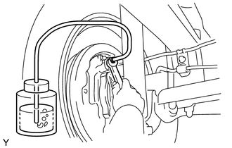
(e) Loosen the bleeder plug.
(f) Select "TRAC Solenoid (SRMF & SRMR)" to drive the solenoids and bleed air from the rear wheel cylinder (step F).
NOTICE:
- Do not depress the brake pedal.
- Keep brake fluid in the reservoir tank above the MIN line during the above procedures.
HINT:
- Brake fluid is sent through the pump.
- To protect the solenoids, the Techstream turns OFF automatically 2 seconds after every solenoid has been turned ON.
(g) Repeat step F until all the air in the brake fluid is bled out.
(h) When the air is completely bled out of the brake fluid through the bleeder plug, tighten the bleeder plug.
Torque:
11 N·m {110 kgf·cm, 8 ft·lbf}
(i) Repeat the above procedures to bleed the other brake line.
(j) Turn the ignition switch to OFF.
(k) Turn the ignition switch to ON.
(l) Clear DTC (see page .gif) ).
).
5. INSPECT FOR BRAKE FLUID LEAK
6. INSPECT FLUID LEVEL IN RESERVOIR
 Installation
INSTALLATION
PROCEDURE
1. INSTALL VACUUM WARNING SWITCH ASSEMBLY (for 2GR-FKS)
Click here
2. INSTALL BRAKE VACUUM CHECK VALVE ASSEMBLY (for 2TR-FE)
(a) Install a new grommet onto the ...

Other materials:
Front Crankshaft Oil Seal
Components
COMPONENTS
ILLUSTRATION
Installation
INSTALLATION
PROCEDURE
1. INSTALL TIMING GEAR CASE OR TIMING CHAIN CASE OIL SEAL
(a) Apply MP grease to the lip of a new timing gear case or timing chain case
oil seal.
(b) Using SST and a hammer, tap in the timing gear case ...
Diagnosis System
DIAGNOSIS SYSTEM
1. CHECK DLC3
(a) Check the DLC3 (See page ).
2. INSPECT BATTERY VOLTAGE
(a) Measure the battery voltage.
Standard Voltage:
11 to 14 V
If the voltage is below 11 V, recharge or replace the battery.
3. SELF-DIAGNOSTIC MODE (OPERATING IGNITION KEY CYLINDER)
(a) Switch to se ...
Pressure Control Solenoid "C" Circuit Open (P079513)
DESCRIPTION
Changing from 1st to 6th is performed by the ECM turning shift solenoid valves
SL1, SL2, SL3 and SL4 on and off. If an open or short circuit occurs in any of the
shift solenoid valves, the ECM controls the remaining normal shift solenoid valves
to allow the vehicle to be operated ...
