Toyota Tacoma (2015-2018) Service Manual: Amplifier Box Speaker Assembly
Components
COMPONENTS
ILLUSTRATION
ILLUSTRATION
Removal
REMOVAL
PROCEDURE
1. PRECAUTION
NOTICE:
After turning the ignition switch off, waiting time may be required before disconnecting the cable from the negative (-) battery terminal. Therefore, make sure to read the disconnecting the cable from the negative (-) battery terminal notices before proceeding with work.
Click here .gif)
2. DISCONNECT CABLE FROM NEGATIVE BATTERY TERMINAL
NOTICE:
When disconnecting the cable, some systems need to be initialized after the cable is reconnected.
Click here
3. REMOVE REAR SEATBACK ASSEMBLY RH
(See page )
4. REMOVE REAR SEATBACK ASSEMBLY LH
(See page )
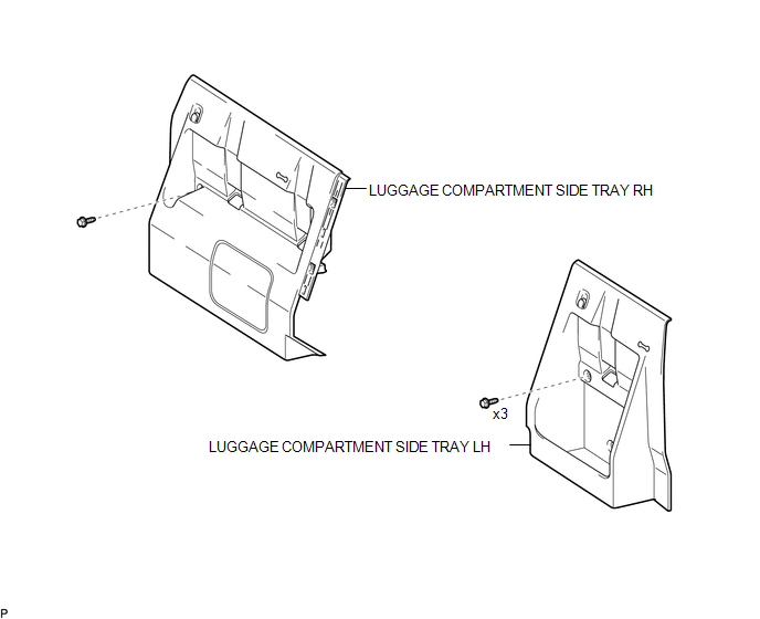
5. REMOVE LUGGAGE COMPARTMENT SIDE TRAY LH
(See page )
6. REMOVE LUGGAGE COMPARTMENT SIDE TRAY RH
(See page )
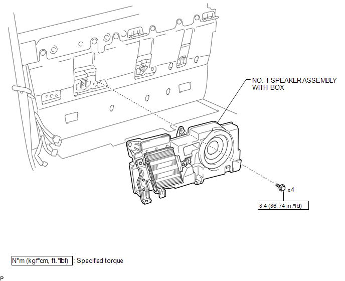
7. REMOVE NO. 1 SPEAKER ASSEMBLY WITH BOX
(a) Disconnect the 4 connectors.
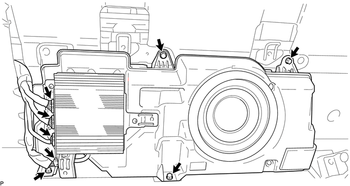
(b) Remove the 4 bolts and the No. 1 speaker assembly with box.
Installation
INSTALLATION
PROCEDURE
1. INSTALL NO. 1 SPEAKER ASSEMBLY WITH BOX
(a) Install the No. 1 speaker assembly with box with the 4 bolts.
Torque:
8.4 N·m {86 kgf·cm, 74 in·lbf}
(b) Connect the 4 connectors.
2. INSTALL LUGGAGE COMPARTMENT SIDE TRAY RH
(See page .gif) )
)
3. INSTALL LUGGAGE COMPARTMENT SIDE TRAY LH
(See page )
4. INSTALL REAR SEATBACK ASSEMBLY LH
(See page )
5. INSTALL REAR SEATBACK ASSEMBLY RH
(See page )
6. CONNECT CABLE TO NEGATIVE BATTERY TERMINAL
Torque:
5.4 N·m {55 kgf·cm, 48 in·lbf}
NOTICE:
When disconnecting the cable, some systems need to be initialized after the cable is reconnected.
Click here
 Audio / Video
...

Other materials:
Front Speed Sensor RH Performance (C1409,C1410)
DESCRIPTION
Refer to DTCs C1401 and C1402 (See page ).
DTC Code
DTC Detection Condition
Trouble Area
C1409
C1410
One of the following conditions is met:
When the vehicle is driven in reverse at a speed of 3 km/h (2
...
Key-off Operation Function Operates even if Operating Conditions are not Satisfied
DESCRIPTION
When the front doors are closed, each power window regulator motor assembly
can control its power window operation for approximately 43 seconds after
the ignition switch is turned from ON to off by receiving operation permission
signals from the main body ECU.
How ...
Diagnosis System
DIAGNOSIS SYSTEM
1. DESCRIPTION
The ECM stores DTCs (Diagnostic Trouble Codes) when trouble occurs on the vehicle.
The diagnosis system allows reading of DTCs stored in the ECM when a the Techstream
is connected to the DLC3 (Data Link Connector 3). If the CRUISE MAIN indicator light
does not ...
