Toyota Tacoma (2015-2018) Service Manual: Transfer Shift Motor Control Circuit Low (P17A9)
DESCRIPTION
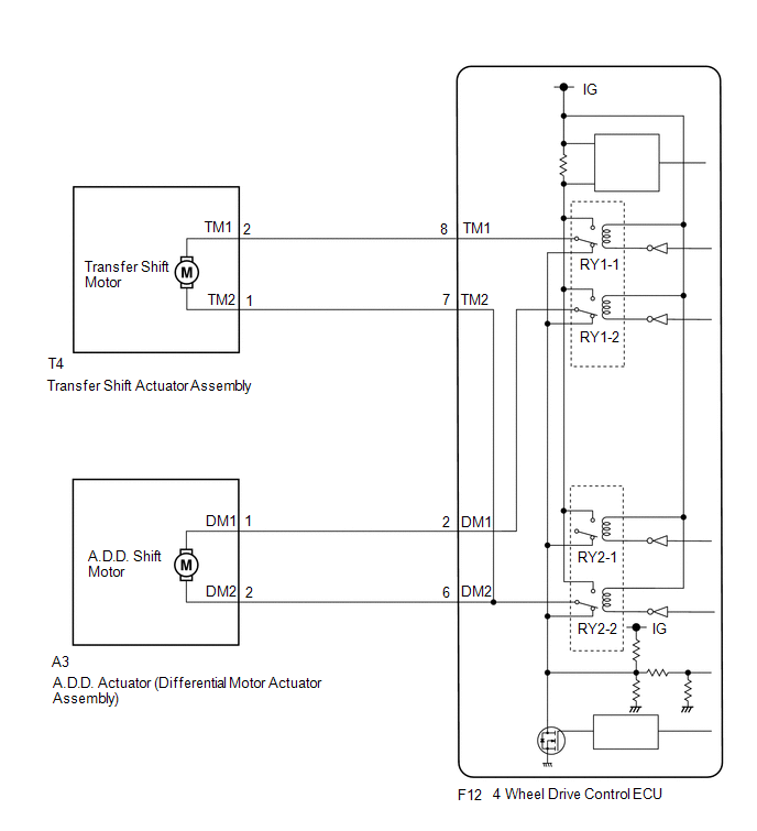
This DTC is output when a short to ground in the transfer shift motor and A.D.D. shift motor drive circuit is detected.
|
DTC No. |
Detection Item |
DTC Detection Condition |
Trouble Area |
|---|---|---|---|
|
P17A9 |
Transfer Shift Motor Control Circuit Low |
|
|
WIRING DIAGRAM
PROCEDURE
|
1. |
CHECK ACTUATOR ASSEMBLY (TRANSFER SHIFT MOTOR OR A.D.D. SHIFT MOTOR) |
(a) Disconnect the 4 wheel drive control ECU connector.
|
(b) Measure the resistance according to the value(s) in the table below. Standard Resistance: Transfer shift actuator assembly side:
|
|
|
Result |
Proceed to |
|---|---|
|
OK |
A |
|
NG (transfer shift actuator assembly side) |
B |
|
NG (A.D.D. actuator (differential vacuum actuator assembly) side) |
C |
| A | .gif) |
REPLACE 4 WHEEL DRIVE CONTROL ECU |
| C | |
GO TO STEP 3 |
|
.gif)
|
2. |
CHECK HARNESS AND CONNECTOR (4 WHEEL DRIVE CONTROL ECU AND TRANSFER SHIFT ACTUATOR ASSEMBLY - BODY GROUND) |
(a) Disconnect the F12 4 wheel drive control ECU connector.
(b) Disconnect the T4 transfer shift actuator assembly connector.
(c) Measure the resistance according to the value(s) in the table below.
Standard Resistance:
|
Tester Connection |
Condition |
Specified Condition |
|---|---|---|
|
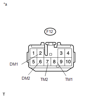
F12-8 (TM1) or T4-2 (TM1) - Body ground |
Always |
10 kΩ or higher |
|
F12-7 (TM2) or T4-1 (TM2) - Body ground |
Always |
10 kΩ or higher |
| OK | |
REPLACE TRANSFER SHIFT ACTUATOR ASSEMBLY |
| NG | |
REPAIR OR REPLACE HARNESS OR CONNECTOR |
|
3. |
CHECK HARNESS AND CONNECTOR (4 WHEEL DRIVE CONTROL ECU AND DIFFERENTIAL VACUUM ACTUATOR ASSEMBLY - BODY GROUND) |
(a) Disconnect the F12 4 wheel drive control ECU connector.
(b) Disconnect the A3 A.D.D. actuator (differential vacuum actuator assembly) connector.
(c) Measure the resistance according to the value(s) in the table below.
Standard Resistance:
|
Tester Connection |
Condition |
Specified Condition |
|---|---|---|
|
F12-2 (DM1) or A3-1 (DM1) - Body ground |
Always |
10 kΩ or higher |
|
F12-6 (DM2) or A3-2 (DM2) - Body ground |
Always |
10 kΩ or higher |
| OK | |
REPLACE DIFFERENTIAL VACUUM ACTUATOR ASSEMBLY |
| NG | |
REPAIR OR REPLACE HARNESS OR CONNECTOR |
 Four Wheel Drive (4WD) Range Signal Circuit Range / Performance (P279E)
DESCRIPTION
When the transfer position switch is switched, the 2-4 terminal and LO terminal
change to one of the following ON/OFF combinations listed in the table below.
Terminal
...
 Transfer Shift Motor Control Circuit High (P17AA)
DESCRIPTION
This DTC is output when a short to B+ in the transfer shift motor and A.D.D.
shift motor drive circuit is detected.
DTC No.
Detection Item
DTC Detectio ...
Other materials:
Passenger Side Buckle Switch Circuit Malfunction (B1771)
DESCRIPTION
The passenger side buckle switch circuit consists of the occupant detection ECU
and the front seat inner belt assembly RH.
DTC B1771 is recorded when a malfunction is detected in the passenger side buckle
switch circuit.
Troubleshoot DTC B1771 first when DTCs B1771 and B1795 are o ...
Network Gateway Ecu
Components
COMPONENTS
ILLUSTRATION
Installation
INSTALLATION
PROCEDURE
1. INSTALL NETWORK GATEWAY ECU
(a) Install the network gateway ECU with the bolt.
Torque:
3.0 N·m {31 kgf·cm, 27 in·lbf}
(b) Connect the connector.
2. INSTALL LOWER INSTRUMENT PANEL ASSEMBLY
(See page )
R ...
Cruise SET Indicator Light Circuit
DESCRIPTION
The ECM illuminates the cruise control SET indicator by sending indicator output
demand signals to the combination meter assembly via CAN communication. The cruise
control SET indicator illuminates when the dynamic radar cruise control system is
controlling vehicle speed. The crui ...
