Toyota Tacoma (2015-2018) Service Manual: Terminals Of Ecu
TERMINALS OF ECU
1. CLEARANCE WARNING ECU ASSEMBLY

(a) Disconnect the C30 connector from the clearance warning ECU assembly.
(b) Measure the voltage and resistance according to the value(s) in the table below.
|
Terminal No. (Symbol) |
Wiring Color |
Terminal Description |
Condition |
Specified Condition |
|---|---|---|---|---|
|
C30-9 (CLSW) - C30-30 (E) |
Y - W-B |
Back sonar or clearance sonar switch assembly power source signal |
Ignition switch ON, back sonar or clearance sonar switch assembly on |
11 to 14 V |
|
C30-9 (CLSW) - C30-30 (E) |
Y - W-B |
Back sonar or clearance sonar switch assembly power source signal |
Ignition switch ON, back sonar or clearance sonar switch assembly off |
Below 1 V |
|
C30-1 (IG) - C30-30 (E) |
P - W-B |
IG power source signal |
Ignition switch off |
Below 1 V |
|
Ignition switch ON |
11 to 14 V |
|||
|
C30-30 (E) - Body ground |
W-B - Body ground |
Ground |
Always |
Below 1 Ω |
(c) Reconnect the C30 connector to the clearance warning ECU assembly.
(d) Measure the voltage and check for pulses according to the value(s) in the table below.
|
Terminal No. (Symbol) |
Wiring Color |
Terminal Description |
Condition |
Specified Condition |
|---|---|---|---|---|
|
C30-22 (BOR) - C30-30 (E) |
BE - W-B |
Power source for rear sensor circuit |
Ignition switch off |
Below 1 V |
|
Ignition switch ON, back sonar or clearance sonar switch assembly on |
7.2 to 8.8 V |
|||
|
C30-13 (ER) - C30-30 (E) |
R - W-B |
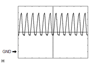
Clearance warning buzzer signal |
Buzzer sounding |
Pulse generation (See waveform 1) |
|
C30-23 (E1) - C30-30 (E) |
B - W-B |
Ground for rear clearance sonar |
Always |
Below 1 V |
|
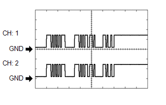
C30-24 (SOR) - C30-30 (E) |
V - W-B |
Rear sensor communication signal (Rear clearance sonar sensor) |
Ignition switch ON, back sonar or clearance sonar switch assembly on, shift lever in R |
Pulse generation (See waveform 2) |
(e) Using an oscilloscope, check waveform 1.
(1) Waveform 1 (Reference)
|
Item |
Content |
|---|---|
|
Terminal No. (Symbol) |
C30-13 (ER) - C30-30 (E) |
|
Tool Setting |
2 V/DIV., 500 ÎĽsec./DIV. |
|
Vehicle Condition |
When sonar detects obstacle (buzzer sounds) |
|
Buzzer volume |
M2 (Medium volume) |
HINT:
The amplitude of the waveform changes according to the set volume.
(f) Using an oscilloscope, check waveform 2.
(1) Waveform 2 (Reference)
|
Item |
Content |
|---|---|
|
Terminal No. (Symbol) |
C30-24 (SOR) - C30-30 (E) |
|
Tool Setting |
5 V/DIV., 1 msec./DIV. |
|
Condition |
Ignition switch ON, back sonar or clearance sonar switch assembly on, shift lever in R |
HINT:
The waveforms for CH1 and CH2 are same.
 Problem Symptoms Table
PROBLEM SYMPTOMS TABLE
HINT:
Use the table below to help determine the cause of problem symptoms.
If multiple suspected areas are listed, the potential causes of the symptoms
are lis ...
 Diagnosis System
DIAGNOSIS SYSTEM
1. DESCRIPTION
(a) When troubleshooting a vehicle with a diagnosis system, the only difference
from the usual troubleshooting procedure is connecting the Techstream to the vehicle ...
Other materials:
Dtc Check / Clear
DTC CHECK / CLEAR
1. CHECK DTC (for TIRE PRESSURE WARNING ECU AND RECEIVER) (USING TECHSTREAM)
(a) Turn the ignition switch off.
(b) Connect the Techstream to the DLC3.
(c) Turn the ignition switch to ON.
(d) Turn the Techstream on.
(e) Enter the following menus: Chassis / Tire Pressure Monito ...
Extension Module Malfunction (B1552,B158A,B15BA)
DESCRIPTION
These DTCs are stored when a malfunction occurs in the stereo component tuner
assembly.
DTC No.
DTC Detection Condition
Trouble Area
B1552
Internal malfunction of the navigation ECU
Stereo component tuner assembl ...
Stop Light Relay Circuit (C1A4B)
DESCRIPTION
The skid control ECU (master cylinder solenoid)*1 or skid control ECU (brake
actuator assembly)*2 sends a stop light operation request signal to the stop light
relay (stop light switch assembly). If the skid control ECU (master cylinder solenoid)*1
or skid control ECU (brake actua ...
