Toyota Tacoma (2015-2018) Service Manual: TC and CG Terminal Circuit
DESCRIPTION
Connecting terminals TC and CG of the DLC3 causes the ECU to display the DTC by blinking the ABS warning light and slip indicator light.
WIRING DIAGRAM
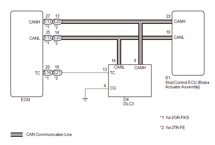
CAUTION / NOTICE / HINT
NOTICE:
When replacing the skid control ECU (brake actuator assembly), perform zero point
calibration and store system information (See page
.gif) ).
).
PROCEDURE
|
1. |
CHECK CAN COMMUNICATION SYSTEM |
(a) Check if CAN communication system DTCs are output (See page
).
|
Result |
Proceed to |
|---|---|
|
DTC is not output |
A |
|
DTC is output |
B |
| B | .gif) |
CHECK CAN COMMUNICATION SYSTEM |
|
.gif)
|
2. |
INSPECT DLC3 |
|
(a) Turn the ignition switch to ON. |
|
(b) Measure the voltage according to the value(s) in the table below.
Standard Voltage:
|
Tester Connection |
Switch Condition |
Specified Condition |
|---|---|---|
|
D4-13 (TC) - D4-4 (CG) |
Ignition switch ON |
11 to 14 V |
|
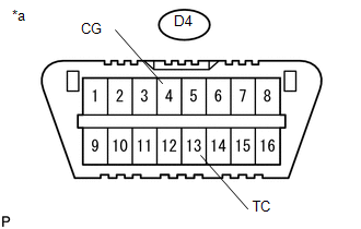
*a |
Front view of DLC3 |
| NG | |
GO TO STEP 4 |
|
|
3. |
REPLACE ECM |
|
(a) Turn the ignition switch off. |
|
(b) Replace the ECM.
- for 2GR-FKS: (See page
)
- for 2TR-FE: (See page
)
(c) Using SST, connect terminals 13 (TC) and 4 (CG) of the DLC3.
SST: 09843-18040
(d) Check that the ABS warning and slip indicator lights are blinking.
OK:
The ABS warning and slip indicator lights are blinking.
Text in Illustration|
*a |
Front view of DLC3 |
| OK | |
END |
| NG | |
REPLACE BRAKE ACTUATOR ASSEMBLY |
|
4. |
CHECK HARNESS AND CONNECTOR (TC of DLC3 - ECM) |
(a) Turn the ignition switch off.
(b) Disconnect the E13*1, E21*2 ECM connector.
- *1: for 2GR-FKS
- *2: for 2TR-FE
(c) Measure the resistance according to the value(s) in the table below.
Standard Resistance:
for 2GR-FKS:|
Tester Connection |
Condition |
Specified Condition |
|---|---|---|
|
D4-13 (TC) - E14-20 (TC) |
Always |
Below 1 Ω |
|
D4-13 (TC) or E14-20 (TC) - Body ground |
Always |
10 kΩ or higher |
|
Tester Connection |
Condition |
Specified Condition |
|---|---|---|
|
D4-13 (TC) - E21-19 (TC) |
Always |
Below 1 Ω |
|
D4-13 (TC) or E21-19 (TC) - Body ground |
Always |
10 kΩ or higher |
| NG | |
REPAIR OR REPLACE HARNESS OR CONNECTOR |
|
|
5. |
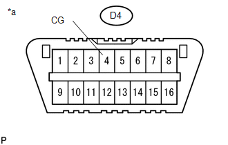
CHECK HARNESS AND CONNECTOR (CG of DLC3 - BODY GROUND) |
|
(a) Measure the resistance according to the value(s) in the table below. Standard Resistance:
|
|
| NG | |
REPAIR OR REPLACE HARNESS OR CONNECTOR |
|
|
6. |
REPLACE ECM |
|
(a) Replace the ECM.
|
|
(b) Using SST, connect terminals 13 (TC) and 4 (CG) of the DLC3.
SST: 09843-18040
(c) Check that the ABS warning and slip indicator lights are blinking.
OK:
The ABS warning and slip indicator lights are blinking.
Text in Illustration|
*a |
Front view of DLC3 |
| OK | |
END |
| NG | |
REPLACE BRAKE ACTUATOR ASSEMBLY |
 Slip Indicator Light does not Come ON
DESCRIPTION
Refer to Slip Indicator Light Remains ON (See page
).
WIRING DIAGRAM
Refer to Slip Indicator Light Remains ON (See page
).
CAUTION / NOTICE / HINT
NOTICE:
When replacing the skid ...
 VSC Buzzer Circuit
DESCRIPTION
The skid control ECU (brake actuator assembly) is connected to the combination
meter via CAN communication.
The combination meter has a built-in VSC warning buzzer:
Sounds inte ...
Other materials:
Stop Light Relay Circuit (C1A4B)
DESCRIPTION
The skid control ECU (master cylinder solenoid)*1 or skid control ECU (brake
actuator assembly)*2 sends a stop light operation request signal to the stop light
relay (stop light switch assembly). If the skid control ECU (master cylinder solenoid)*1
or skid control ECU (brake actua ...
If the vehicle becomes stuck
Carry out the following procedures if the tires spin or the vehicle becomes
stuck in mud, dirt, or snow.
Stop the engine. Set the parking
brake and put the shift lever in P (vehicles with an automatic transmission) or
N (vehicles with a manual transmission).
Remove the mud, snow, or sand f ...
Body
General Maintenance
GENERAL MAINTENANCE
PROCEDURE
1. TIGHTEN BOLTS AND NUTS ON CHASSIS AND BODY
(a) Tighten the bolts and nuts on the chassis parts listed below, if necessary.
Front axle and suspension
Drive train
Rear axle and suspension
Brake system
Engine mounting
...
