Toyota Tacoma (2015-2018) Service Manual: System Diagram
SYSTEM DIAGRAM
 Parts Location
PARTS LOCATION
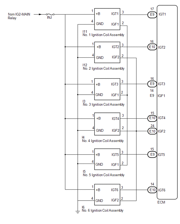
ILLUSTRATION
ILLUSTRATION
ILLUSTRATION
...
 On-vehicle Inspection
ON-VEHICLE INSPECTION
CAUTION / NOTICE / HINT
HINT:
Perform "Inspection After Repair" after replacing an ignition coil assembly or
spark plug (See page ).
PROCEDURE
1. PERFORM SPARK ...
Other materials:
Installation
INSTALLATION
CAUTION / NOTICE / HINT
HINT:
Use the same procedure for both the LH and RH sides.
The procedure described below is for the LH side.
PROCEDURE
1. INSTALL HEADLIGHT ASSEMBLY
(a) Connect the connectors.
(b) Engage the clamp to install the headlight assembly.
(c) ...
Symbols used in illustrations
The symbol of a circle with a slash
through it means “Do not”, “Do not do this”, or “Do not let this happen”.
Arrows indicating operations
Indicates the action (pushing, turning,
etc.) used to operate switches and other devices.
Indicates the outcome of an operation
(e.g. a ...
Transmission Fluid Temperature Sensor "A" Circuit Low Input (P0712,P0713)
DESCRIPTION
The No. 1 ATF temperature sensor converts the fluid temperature into a resistance
value for use by the ECM.
The ECM applies a voltage to the temperature sensor through terminal THO1 of
the ECM.
The sensor resistance changes with the ATF temperature. As the temperature becomes
hi ...
