Toyota Tacoma (2015-2018) Service Manual: System Diagram
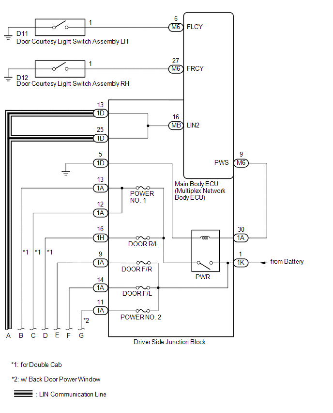
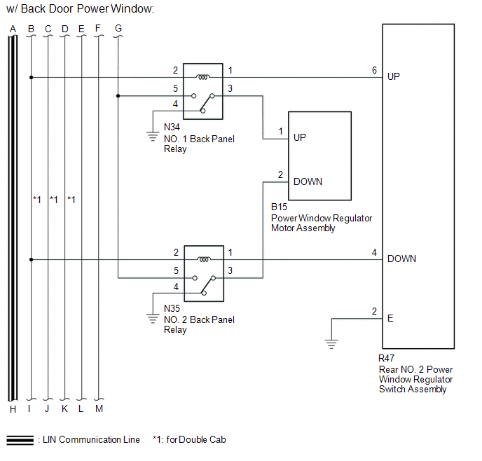
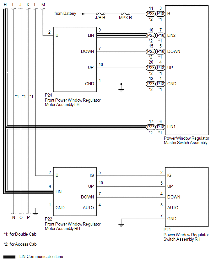
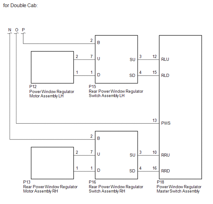
SYSTEM DIAGRAM
 Communication Table
|
Transmitting ECU |
Receiving ECU |
Signal |
Communication Method |
|---|---|---|---|
|
Power Window Regulator Master Switch Assembly |
Power Window Regulator Motor Assembly (for Driver Door) |
Power Window Regulator Motor Assembly (for Front Passenger Door) |
LIN |
|
Power Window Regulator Motor Assembly (for Front Passenger Door) |
Power window remote up and down signal |
LIN |
|
|
Main body ECU (multiplex network body ECU) |
|
Power window operation permission signal |
LIN |
 System Description
SYSTEM DESCRIPTION
1. POWER WINDOW CONTROL SYSTEM DESCRIPTION
(a) The power window control system controls the power window operation using
the power window regulator motors. The main controls of ...
 Customize Parameters
CUSTOMIZE PARAMETERS
PROCEDURE
1. CUSTOMIZE POWER WINDOW CONTROL SYSTEM
HINT:
The following items can be customized.
NOTICE:
When the customer requests a change in a function, first make ...
Other materials:
Vehicle Speed Signal Circuit between Stereo Component Amplifier and Combination
Meter
DESCRIPTION
The stereo component amplifier assembly receives a vehicle speed signal from
the combination meter assembly to control the ASL function.
HINT:
A voltage of 12 V or 5 V is output from each ECU and then input to the
combination meter assembly. The signal is changed to a pu ...
On-vehicle Inspection
ON-VEHICLE INSPECTION
PROCEDURE
1. INSPECT SHIFT LEVER POSITION
(a) When moving the shift lever from P to each position with the ignition switch
ON and the brake pedal depressed, check that the shift lever moves smoothly and
correctly into position.
(b) Start the engine and check that the ve ...
Communication Malfunction between ECUs Connected by LIN (B2785)
DESCRIPTION
The certification ECU (smart key ECU assembly) monitors communication between
all the ECUs connected to the certification bus lines. When the certification ECU
(smart key ECU assembly) detects errors in communication with all the ECUs connected
to the certification bus lines at a ...
