Toyota Tacoma (2015-2018) Service Manual: Repair
REPAIR
PROCEDURE
1. REPAIR INTAKE VALVE SEATS
NOTICE:
- Repair the intake valve seat while checking the seating position.
- Keep the lip free of foreign matter.
|
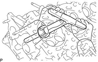
(a) Using a 45° cutter, resurface the valve seat so that the valve seat width is more than the specification. |
|
|
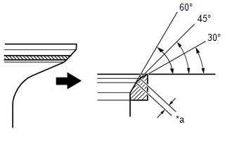
(b) Using 30° and 60° cutters, correct the valve seat so that the intake valve contacts the entire circumference of the seat. The contact should be in the center of the intake valve seat, and the intake valve seat width should be maintained within the specified range around the entire circumference of the intake valve seat. Text in Illustration
Standard width: 1.1 to 1.5 mm (0.0433 to 0.0591 in.) |
|
(c) Hand-lap the intake valve and intake valve seat with an abrasive compound.
(d) Check the intake valve seating position.
2. REPAIR EXHAUST VALVE SEATS
NOTICE:
- Repair the seat while checking the seating position.
- Keep the lip free of foreign matter.
|
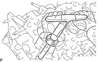
(a) Using a 45° cutter, resurface the valve seat so that the valve seat width is more than the specification. |
|
|
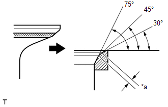
(b) Using 30° and 75° cutters, correct the exhaust valve seat so that the exhaust valve contacts the entire circumference of the seat. The contact should be in the center of the exhaust valve seat, and the exhaust valve seat width should be maintained within the specified range around the entire circumference of the exhaust valve seat. Text in Illustration
Standard width: 1.3 to 1.7 mm (0.0512 to 0.0669 in.) |
|
(c) Hand-lap the exhaust valve and exhaust valve seat with an abrasive compound.
(d) Check the exhaust valve seating position.
 Reassembly
REASSEMBLY
CAUTION / NOTICE / HINT
HINT:
Perform "Inspection After Repairs" after replacing the cylinder head sub-assembly
or cylinder head LH (See page ).
PROCEDURE
1. INSTALL SPARK ...

Other materials:
Fender Panel Mudguard
Components
COMPONENTS
ILLUSTRATION
ILLUSTRATION
Installation
INSTALLATION
CAUTION / NOTICE / HINT
HINT:
Use the same procedure for the RH side and LH side.
The following procedure is for the LH side.
PROCEDURE
1. INSTALL FRONT FENDER MUDGUARD
(a) Install the fron ...
Short to GND in Outer Mirror Indicator(Slave) (C1AB3)
DESCRIPTION
This DTC is stored when the blind spot monitor sensor RH detects a ground short
in the blind spot monitor indicator RH.
DTC Code
DTC Detection Condition
Trouble Area
C1AB3
With the blind spot monitor main switch assembly (w ...
Transmitter ID not Received in Main Mode (C2126/26)
DESCRIPTION
After all transmitter IDs are registered, DTC C2126/26 is stored in the tire
pressure warning ECU and receiver and the tire pressure warning light blinks for
1 minute and then illuminates.
When the tire pressure warning ECU and receiver successfully receives radio waves
from all ...
