Toyota Tacoma (2015-2018) Service Manual: Removal
REMOVAL
CAUTION / NOTICE / HINT
CAUTION:
Some of these service operations affect the SRS airbag system. Read the precautionary
notices concerning the SRS airbag system before servicing (See page
.gif) ).
).
HINT:
- Use the same procedure for both the RH and LH sides.
- The procedure described below is for the LH side.
PROCEDURE
1. PRECAUTION
CAUTION:
Be sure to read Precaution thoroughly before servicing (See page
).
NOTICE:
After turning the ignition switch off, waiting time may be required before disconnecting the cable from the negative (-) battery terminal. Therefore, make sure to read the disconnecting the cable from the negative (-) battery terminal notices before proceeding with work.
Click here
2. DISCONNECT CABLE FROM NEGATIVE BATTERY TERMINAL
CAUTION:
Wait at least 90 seconds after disconnecting the cable from the negative (-) battery terminal to disable the SRS system.
NOTICE:
When disconnecting the cable, some systems need to be initialized after the cable is reconnected.
Click here
3. REMOVE FRONT DOOR SCUFF PLATE
4. REMOVE REAR DOOR SCUFF PLATE
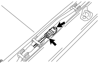
5. REMOVE SIDE AIRBAG SENSOR ASSEMBLY
(a) Disconnect the connector from the side airbag sensor.
NOTICE:
When disconnecting any airbag connector, take care not to damage the airbag wire harness.
(1) Push and hold the white housing lock, and slide the yellow outer connector locking sleeve.
.png)
(2) Push and hold the white housing lock again, and slide the yellow outer connector locking sleeve to disconnect the connector.
(b) Remove the bolt and side airbag sensor.
NOTICE:
Loosen the bolt while holding the door side airbag sensor because the side airbag sensor pin (stopper) is easily damaged.
 Installation
INSTALLATION
CAUTION / NOTICE / HINT
CAUTION:
Some of these service operations affect the SRS airbag system. Read the precautionary
notices concerning the SRS airbag system before servicing (See ...

Other materials:
Parking Brake Switch
Components
COMPONENTS
ILLUSTRATION
Inspection
INSPECTION
PROCEDURE
1. INSPECT PARKING BRAKE SWITCH ASSEMBLY
(a) Check the resistance.
(1) Measure the resistance according to the value(s) in the table below.
Text in Illustration
On
Off
...
System Diagram
SYSTEM DIAGRAM
Communication Table
Sender
Receiver
Signal
Communication Method
Airbag sensor assembly
Main body ECU
Front seat inner belt assembly LH buckle switch
CAN
Combination mete ...
Cruise Control Switch Circuit
DESCRIPTION
This circuit sends signals to the ECM depending on the cruise control main switch
condition.
The battery supplies the positive (+) battery voltage to the cruise control main
switch. Then terminal CCS of the ECM receives the voltage as the signal according
to the switch condition. ...
