Toyota Tacoma (2015-2018) Service Manual: Removal
REMOVAL
PROCEDURE
1. PRECAUTION
CAUTION:
Be sure to read Precaution thoroughly before servicing (See page
.gif) ).
).
NOTICE:
After turning the ignition switch off, waiting time may be required before disconnecting the cable from the negative (-) battery terminal. Therefore, make sure to read the disconnecting the cable from the negative (-) battery terminal notices before proceeding with work.
Click here
2. DISCONNECT CABLE FROM NEGATIVE BATTERY TERMINAL
CAUTION:
Wait at least 90 seconds after disconnecting the cable from the negative (-) battery terminal to prevent airbag and seat belt pretensioner activation.
NOTICE:
When disconnecting the cable, some systems need to be initialized after the cable is reconnected.
Click here
3. REMOVE INSTRUMENT SIDE PANEL RH
4. REMOVE GLOVE COMPARTMENT PLATE
5. REMOVE LOWER NO. 2 INSTRUMENT PANEL AIRBAG ASSEMBLY
|
(a) Remove the 3 bolts. Text in Illustration
|
|
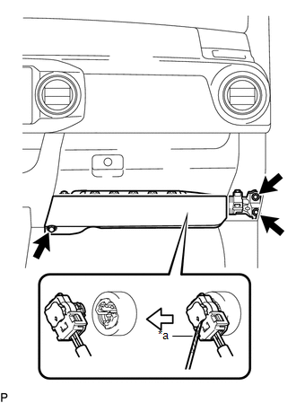
(b) Using a screwdriver with its tip wrapped in protective tape, release the airbag connector lock.
(c) Disconnect the airbag connector to remove the lower No. 2 instrument panel airbag assembly.
NOTICE:
When handling the airbag connector, take care not to damage the airbag wire harness.
 On-vehicle Inspection
ON-VEHICLE INSPECTION
PROCEDURE
1. INSPECT LOWER NO. 2 INSTRUMENT PANEL AIRBAG ASSEMBLY (for Vehicle not Involved
in Collision)
(a) Perform a diagnostic system check (See page
).
...
 Disposal
DISPOSAL
CAUTION / NOTICE / HINT
CAUTION:
Before performing pre-disposal deployment of any SRS part, review and closely
follow all applicable environmental and hazardous material regulations. Pre ...
Other materials:
Data List / Active Test
DATA LIST / ACTIVE TEST
1. DATA LIST
HINT:
Using the Techstream to read the Data List allows the values or states of switches,
sensors, actuators and other items to be read without removing any parts. This non-intrusive
inspection can be very useful because intermittent conditions or signals ...
All Doors LOCK/UNLOCK Functions do not Operate Via Door Control Switch
DESCRIPTION
The main body ECU (multiplex network body ECU) receives switch signals from the
door control switch assembly on the front passenger door and activates the door
lock motor on each door according to these signals.
WIRING DIAGRAM
PROCEDURE
1.
READ VALUE USIN ...
Confirm Vehicle Headunit Functionality
PROCEDURE
1.
CHECK CUSTOMER'S CELLULAR PHONE COMPATIBILITY
(a) Go to TIS "Bluetooth" Compatibility Portal and check if the cellular phone
is compatible.
Result
Result
Proceed to
Cellular phone is compatible
...
