Toyota Tacoma (2015-2018) Service Manual: Removal
REMOVAL
PROCEDURE
1. REMOVE FRONT DOOR SCUFF PLATE LH (for Double Cab)
Click here .gif)
2. REMOVE FRONT DOOR SCUFF PLATE LH (for Access Cab)
Click here
3. REMOVE COWL SIDE TRIM BOARD LH
Click here
4. REMOVE INSTRUMENT CLUSTER CENTER FINISH PANEL SUB-ASSEMBLY
Click here
5. REMOVE INSTRUMENT CLUSTER FINISH PANEL ASSEMBLY
Click here
6. REMOVE INSTRUMENT PANEL LOWER FINISH PANEL SUB-ASSEMBLY
Click here
7. REMOVE NAVIGATION RECEIVER ASSEMBLY WITH BRACKET (w/ Navigation System)
Click here
8. REMOVE RADIO AND DISPLAY RECEIVER ASSEMBLY WITH BRACKET (w/o Navigation System)
Click here
9. REMOVE AIR CONDITIONING CONTROL ASSEMBLY
|
(a) Disengage the 8 clips. |
|
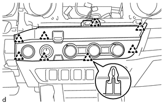
(b) Disconnect the connectors to remove the air conditioning control assembly.
10. REMOVE ENGINE SWITCH
Click here
11. REMOVE TRANSFER POSITION SWITCH (for 4WD)
Click here
 Installation
INSTALLATION
PROCEDURE
1. INSTALL TRANSFER POSITION SWITCH (for 4WD)
Click here
2. INSTALL ENGINE SWITCH
Click here
3. INSTALL AIR CONDITIONING CONTROL ASSEMBLY
(a) Connect the connectors.
...

Other materials:
Daytime Running Light Relay
Inspection
INSPECTION
PROCEDURE
1. INSPECT NO. 1 DAY TIME RUNNING LIGHT RELAY
(a) Check the resistance.
(1) Measure the resistance according to the value(s) in the table below.
Standard:
Tester Connection
Condition
Specified ...
Precaution
PRECAUTION
1. The type of ignition switch used on this model differs depending on the specifications
of the vehicle. The expressions listed in the table below are used in this section.
Expression
Ignition Switch (Position)
Engine Switch (Condition)
...
Rear Door Courtesy Switch
Inspection
INSPECTION
PROCEDURE
1. INSPECT REAR DOOR COURTESY SWITCH
(a) Check the resistance.
(1) Measure the resistance using an ohmmeter, and check the results in accordance
with the value( s) in the table below.
Standard:
Tester Connection
Condition
S ...
