Toyota Tacoma (2015-2018) Service Manual: PTC Heater Circuit
DESCRIPTION
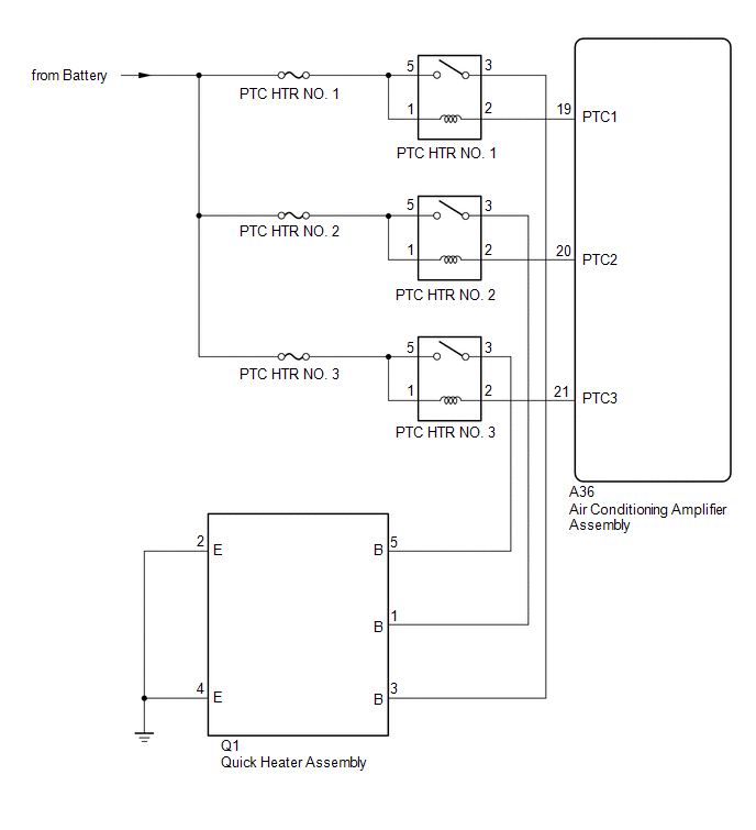
PTC HTR heater relays are closed in accordance with signals from the air conditioning amplifier assembly and power is supplied to the quick heater assembly installed on the radiator heater unit.
WIRING DIAGRAM
CAUTION / NOTICE / HINT
NOTICE:
Inspect the fuses for circuits related to this system before performing the following inspection procedure.
PROCEDURE
|
1. |
PERFORM ACTIVE TEST USING TECHSTREAM |
(a) Connect the Techstream to the DLC3.
(b) Turn the ignition switch to ON.
(c) Turn the Techstream on.
(d) Enter the following menus: Body Electrical / Air Conditioner / Active Test.
(e) Check the operation by referring to the table below.
Air Conditioner|
Tester Display |
Test Part |
Control Range |
Diagnostic Note |
|---|---|---|---|
|
Heater Active Level |
Quick heater assembly |
Min.: 0, Max.: 3 |
- |
OK:
Heater Active Level changes normally.
| NG | .gif) |
PROCEED TO NEXT SUSPECTED AREA SHOWN IN PROBLEM SYMPTOMS TABLE |
|
.gif)
|
2. |
INSPECT PTC HTR RELAY |
(a) Remove the PTC HTR relays.
(b) Inspect the PTC HTR relays (See page .gif) ).
).
| NG | |
REPLACE PTC HTR RELAY |
|
|
3. |
CHECK HARNESS AND CONNECTOR (PTC HTR RELAY - POWER SOURCE CIRCUIT) |
(a) Remove the PTC HTR relays.
(b) Measure the voltage according to the value(s) in the table below.
Standard Voltage:
PTC HTR NO. 1|
Tester Connection |
Condition |
Specified Condition |
|---|---|---|
|
PTC HTR NO. 1-1 - Body ground |
Always |
11 to 14 V |
|
PTC HTR NO. 1-5 - Body ground |
Always |
11 to 14 V |
|
Tester Connection |
Condition |
Specified Condition |
|---|---|---|
|
PTC HTR NO. 2-1 - Body ground |
Always |
11 to 14 V |
|
PTC HTR NO. 2-5 - Body ground |
Always |
11 to 14 V |
|
Tester Connection |
Condition |
Specified Condition |
|---|---|---|
|
PTC HTR NO. 3-1 - Body ground |
Always |
11 to 14 V |
|
PTC HTR NO. 3-5 - Body ground |
Always |
11 to 14 V |
| NG | |
REPAIR OR REPLACE HARNESS OR CONNECTOR |
|
|
4. |
CHECK HARNESS AND CONNECTOR (PTC HTR RELAY - AIR CONDITIONING AMPLIFIER ASSEMBLY) |
(a) Remove the PTC HTR relays.
(b) Disconnect the A36 air conditioning amplifier assembly connector.
(c) Measure the resistance according to the value(s) in the table below.
Standard Resistance:
PTC HTR NO. 1|
Tester Connection |
Condition |
Specified Condition |
|---|---|---|
|
PTC HTR NO. 1-2 - A36-19 (PTC1) |
Always |
Below 1 Ω |
|
PTC HTR NO. 1-2 or A36-19 (PTC1) - Body ground |
Always |
10 kΩ or higher |
|
Tester Connection |
Condition |
Specified Condition |
|---|---|---|
|
PTC HTR NO. 2-2 - A36-20 (PTC2) |
Always |
Below 1 Ω |
|
PTC HTR NO. 2-2 or A36-20 (PTC2) - Body ground |
Always |
10 kΩ or higher |
|
Tester Connection |
Condition |
Specified Condition |
|---|---|---|
|
PTC HTR NO. 3-2 - A36-21 (PTC3) |
Always |
Below 1 Ω |
|
PTC HTR NO. 3-2 or A36-21 (PTC3) - Body ground |
Always |
10 kΩ or higher |
| NG | |
REPAIR OR REPLACE HARNESS OR CONNECTOR |
|
|
5. |
CHECK HARNESS AND CONNECTOR (QUICK HEATER ASSEMBLY - PTC HTR RELAY AND BODY GROUND) |
(a) Remove the PTC HTR relays.
(b) Disconnect the Q1 quick heater assembly connector.
(c) Measure the resistance according to the value(s) in the table below.
Standard Resistance:
PTC HTR NO. 1|
Tester Connection |
Condition |
Specified Condition |
|---|---|---|
|
PTC HTR NO. 1-3 - Q1-3 (B) |
Always |
Below 1 Ω |
|
Q1-2 (E) - Body ground |
Always |
Below 1 Ω |
|
Q1-4 (E) - Body ground |
Always |
Below 1 Ω |
|
PTC HTR NO. 1-3 or Q1-3 (B) - Body ground |
Always |
10 kΩ or higher |
|
Tester Connection |
Condition |
Specified Condition |
|---|---|---|
|
PTC HTR NO. 2-3 - Q1-1 (B) |
Always |
Below 1 Ω |
|
Q1-2 (E) - Body ground |
Always |
Below 1 Ω |
|
PTC HTR NO. 2-3 or Q1-1 (B) - Body ground |
Always |
10 kΩ or higher |
|
Tester Connection |
Condition |
Specified Condition |
|---|---|---|
|
PTC HTR NO. 3-3 - Q1-5 (B) |
Always |
Below 1 Ω |
|
Q1-4 (E) - Body ground |
Always |
Below 1 Ω |
|
PTC HTR NO. 3-3 or Q1-5 (B) - Body ground |
Always |
10 kΩ or higher |
| NG | |
REPAIR OR REPLACE HARNESS OR CONNECTOR |
|
|
6. |
INSPECT QUICK HEATER ASSEMBLY |
(a) Remove the quick heater assembly (See page
).
(b) Inspect the quick heater assembly (See page
).
| OK | |
REPLACE AIR CONDITIONING AMPLIFIER ASSEMBLY |
| NG | |
REPLACE QUICK HEATER ASSEMBLY |
 IG Power Source Circuit
DESCRIPTION
The main power source is supplied to the air conditioning amplifier assembly
when the ignition switch is turned to ON.
The power is used for operating the air conditioning amplifier as ...
 Back-up Power Source Circuit
DESCRIPTION
The back-up power source circuit for the air conditioning amplifier assembly
is shown below. Power is supplied even when the ignition switch is off. The power
is used for diagnostic t ...
Other materials:
How To Proceed With Troubleshooting
CAUTION / NOTICE / HINT
HINT:
Use these procedure to troubleshoot the seat belt warning system.
*: Use the Techstream.
PROCEDURE
1.
VEHICLE BROUGHT TO WORKSHOP
NEXT
2 ...
Center Airbag Sensor Assembly
Components
COMPONENTS
ILLUSTRATION
On-vehicle Inspection
ON-VEHICLE INSPECTION
PROCEDURE
1. INSPECT AIRBAG SENSOR ASSEMBLY (for Vehicle not Involved in Collision)
(a) Perform a diagnostic system check (See page
).
2. INSPECT AIRBAG SENSOR ASSEMBLY (for Vehicle Involved in Collision a ...
Installation
INSTALLATION
PROCEDURE
1. INSTALL FORWARD RECOGNITION CAMERA
NOTICE:
When replacing the forward recognition camera, replace it with a new
one.
Do not touch the camera lens. If the camera lens has been touched, do
not use the forward recognition camera.
If the forward reco ...
