Toyota Tacoma (2015-2018) Service Manual: Parking Brake Switch Circuit
DESCRIPTION
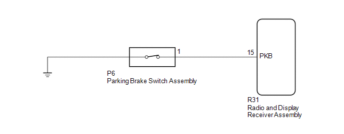
This circuit is from the parking brake switch assembly to the radio and display receiver assembly.
WIRING DIAGRAM
PROCEDURE
|
1. |
CHECK VEHICLE SIGNAL |
|
(a) Display the "Vehicle Signal Check Mode" screen (See page
|
|
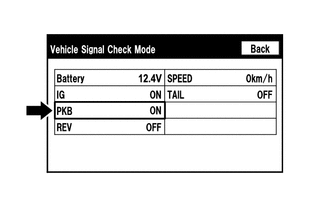
(b) Check that the display changes between ON and OFF according to the parking brake operation.
OK:
|
Parking Brake Condition |
Display |
|---|---|
|
Applied |
ON |
|
Released |
OFF |
HINT:
This display is updated once per second. As a result, it is normal for the display to lag behind the actual parking brake operation.
| OK | .gif) |
PROCEED TO NEXT SUSPECTED AREA SHOWN IN PROBLEM SYMPTOMS TABLE |
|
.gif)
|
2. |
CHECK HARNESS AND CONNECTOR (RADIO AND DISPLAY RECEIVER ASSEMBLY - PARKING BRAKE SWITCH ASSEMBLY) |
(a) Disconnect the R31 radio and display receiver assembly connector.
(b) Disconnect the P6 parking brake switch assembly connector.
(c) Measure the resistance according to the value(s) in the table below.
Standard Resistance:
|
Tester Connection |
Condition |
Specified Condition |
|---|---|---|
|
R31-15 (PKB) - P6-1 |
Always |
Below 1 Ω |
|
R31-15 (PKB) - Body ground |
Always |
10 kΩ or higher |
| NG | |
REPAIR OR REPLACE HARNESS OR CONNECTOR |
|
|
3. |
INSPECT PARKING BRAKE SWITCH ASSEMBLY |
(a) Remove the parking brake switch assembly.
(b) Inspect the parking brake switch assembly (See page
.gif) ).
).
| OK | |
PROCEED TO NEXT SUSPECTED AREA SHOWN IN PROBLEM SYMPTOMS TABLE |
| NG | |
REPLACE PARKING BRAKE SWITCH ASSEMBLY |
 Illumination Circuit
DESCRIPTION
Power is supplied to the radio and display receiver assembly and steering pad
switch assembly illumination when the light control switch is in the TAIL or HEAD
position.
WIRING DIAGR ...
 Speaker Circuit
DESCRIPTION
If there is a short in a speaker circuit, the radio and display receiver
assembly detects it and stops output to the speakers.
Thus sound cannot be heard from the speakers ...
Other materials:
Skid Control Buzzer Circuit (C1A4A)
DESCRIPTION
Based on dynamic radar cruise control system operation, the forward recognition
camera provides warnings to the driver by sounding the skid control buzzer.
DTC C1A4A is stored when a malfunction is detected in the skid control buzzer
circuit.
DTC No.
Detectio ...
System Description
SYSTEM DESCRIPTION
1. SYSTEM DESCRIPTION
(a) The Electronic Controlled Automatic Transmission (ECT) is an automatic transmission
that has its shift timing electronically controlled by the ECM. The ECM detects
electrical signals that indicate engine and driving conditions, and controls the
sh ...
Precaution
PRECAUTION
1. IGNITION SWITCH EXPRESSIONS
(a) The type of ignition switch used on this model differs according to the specifications
of the vehicle. The expressions listed in the table below are used in this section.
Expression
Ignition Switch (Position)
Engine ...
